THDP-TMDP_Instructions-077054003.pdf - 第48页
DC gain Accuracy W ARNING: Dangerous voltages will be present on the calibration generator output terminals and connection cables. Always verify that the generator is in the standby mode before you make any connections t…
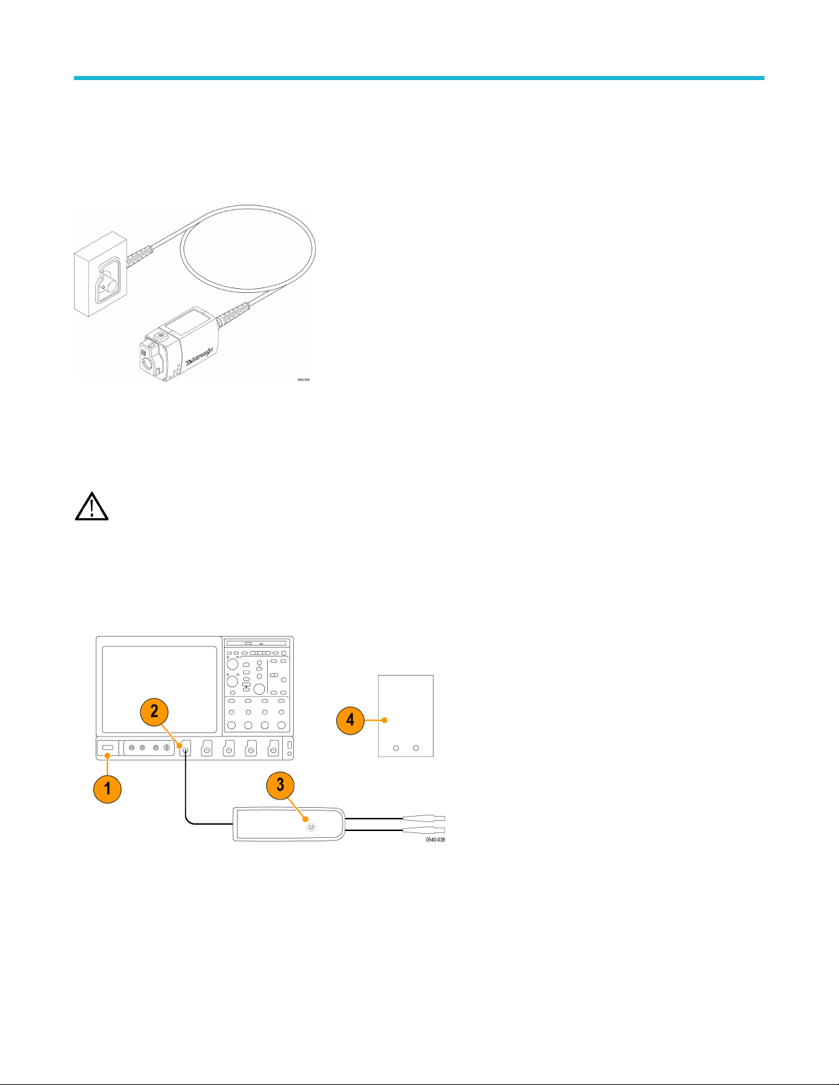
TekVPI Calibration Fixture
This calibration fixture is required to complete a performance verification and gain accuracy adjustment procedures on the probes. It
provides power to the probe and routes the probe output signal out through an SMA connector on the back of the fixture. The signal can
then be measured with another instrument, such as a precision DMM, to check and adjust the gain accuracy of the probe. Order T
ektronix
part number 067-1701-xx.
Figure 15: TekVPI calibration fixture
T
est procedures
WARNING: These procedures require the application of high voltage to the inputs of the probes. Only qualified personnel
should perform any testing with voltage levels exceeding 30 V
rms
. All pertinent safety rules and guidelines for elevated voltage
measurements should be followed and adhered to.
Test setup
1. T
urn on the oscilloscope.
2. Connect the probe to any channel of the oscilloscope.
3. Verify that the LEDs light on the probe.
4. T
urn on the remaining test equipment and let the probe and equipment warm up for 20 minutes.
5. Make a copy of the test record to tabulate the test results. See Test record on page 50.
Performance verification
High Voltage Differential Probes THDP0100/0200 and TMDP0200 User Manual 47
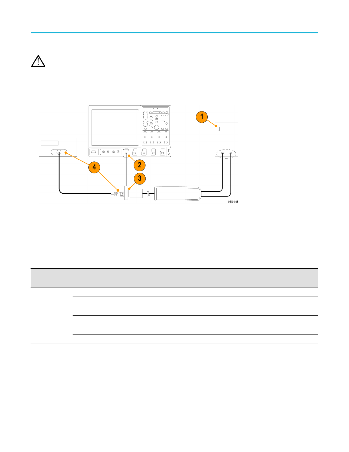
DC gain Accuracy
WARNING: Dangerous voltages will be present on the calibration generator output terminals and connection cables. Always verify
that the generator is in the standby mode before you make any connections to the generator
.
1. V
erify that the generator output is off.
2. Connect the probe calibration fixture to any channel (1–4) on the oscilloscope.
3. Connect the probe output to the probe calibration fixture and the probe inputs to the generator.
4. Connect the output of the probe calibration fixture to the inputs of the DMM, using coax cables and adapters. Set the DMM to AC volts.
5. Set the probe attenuation to the lower range for the probe that you are testing. See T
able 10 on page 48.
6. Set the generator square wave output frequency and RMS voltage (main display) to the values shown in the table for the probe that
you are testing.
7. Enable the generator output and record the probe output (as displayed on the DMM) in the test record.
8. Disable the generator output.
9. Set the probe attenuation to the next range and then repeat steps 6 on page 48 through 8 on page 48.
Table 10: DC gain accuracy equipment settings
Probe Generator output Probe output voltage
Model Range Voltage (rms) Frequency Expected (rms) Measured (rms)
THDP0100 600 V 75 V 100 Hz 750 mV ±15 mV
6000 V 75 V 100 Hz 75 mV ±15 mV
THDP0200 150 V 25 V 100 Hz 500 mV ±10 mV
1500 V 75 V 100 Hz 150 mV ±3 mV
TMDP0200 75 V 20 V 100 Hz 800 mV ±16 mV
750 V 60 V 100 Hz 240 mV ±4.8 mV
Performance verification
48
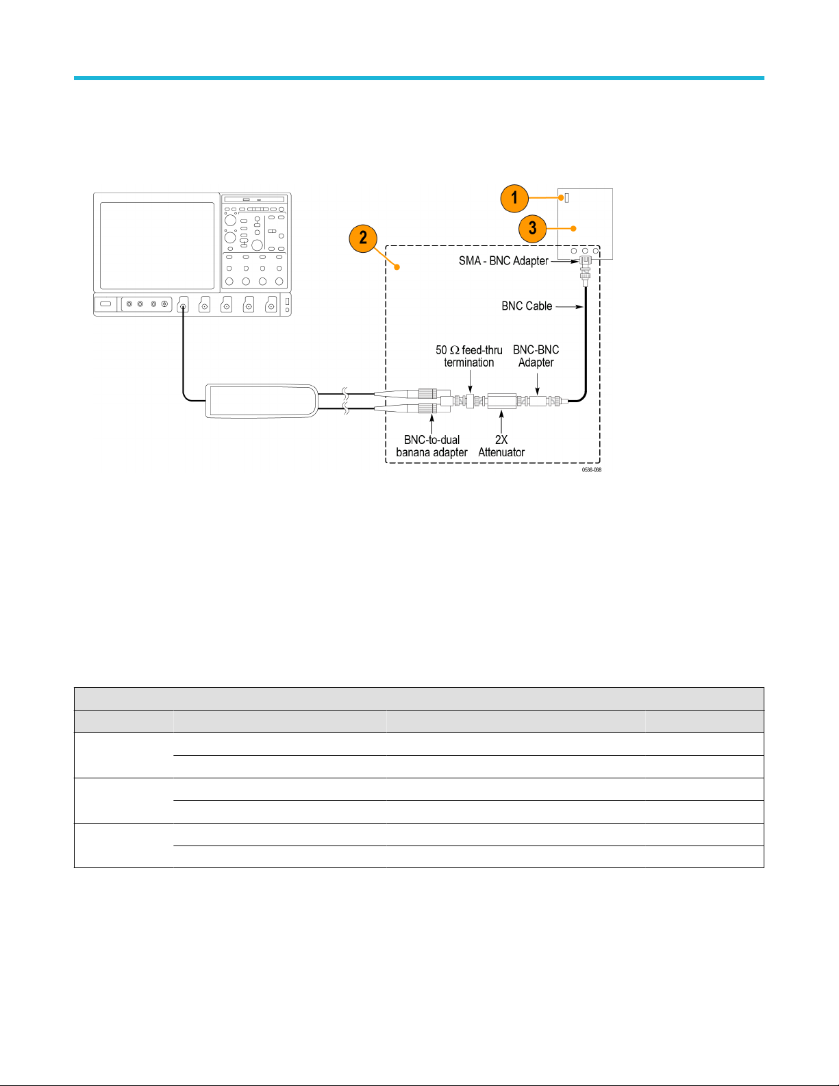
Rise time
1. V
erify that the pulse generator output is off and then connect the probe to the oscilloscope.
2. Connect the probe inputs, through the adapters shown below, to the pulse generator output. Set the probe input leads straight and
parallel for best signal response.
3. Set the output of the pulse generator to 50 V
, 1 kHz, and a 200 ns pulse output. (The probe input voltage will be 25 V due to the 2X
attenuator in the circuit.)
4. Set the oscilloscope to 5 V/div, 10 ns/div, BW = full, average = 16.
5. Set the probe bandwidth to full and the attenuation to the first range listed in the table.
6. Enable the generator output and check that the rise time does not exceed the target rise time value listed in the table. Use the
auto-measure feature of the oscilloscope to determine the rise time.
7. Record the rise time in the test record.
8. Set the probe attenuation to the next range and adjust the vertical volts/div to display the signal.
9. Record the rise time in the test record and disable the generator output.
Table 11: Rise time test equipment settings
Probe Generator output Measurement
Model Range Voltage Frequency Target Measured
THDP0100 600 V 50 V 1 kHz ≤3.6 ns
6000 V 50 V 1 kHz ≤3.6 ns
THDP0200 150 V 50 V 1 kHz ≤2.4 ns
1500 V 50 V 1 kHz ≤2.0 ns
TMDP0200 75 V 50 V 1 kHz ≤2.4 ns
750 V 50 V 1 kHz ≤2.0 ns
Performance verification
High Voltage Differential Probes THDP0100/0200 and TMDP0200 User Manual 49