THDP-TMDP_Instructions-077054003.pdf - 第50页
T est record Photocopy this test record for recording the results of the performance verification procedures. T able 12: THDP and TMDP Series probes test record Probe Model: Probe Serial Number: T emperature: Certificate…
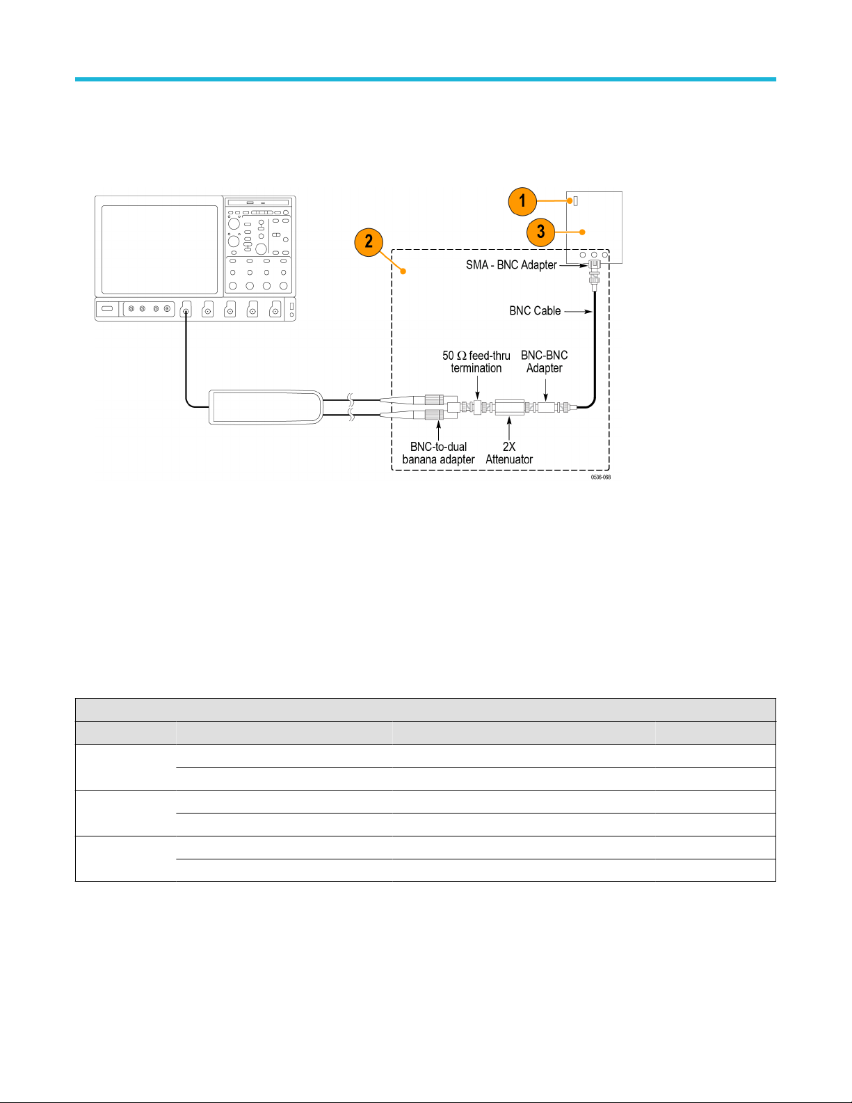
Rise time
1. V
erify that the pulse generator output is off and then connect the probe to the oscilloscope.
2. Connect the probe inputs, through the adapters shown below, to the pulse generator output. Set the probe input leads straight and
parallel for best signal response.
3. Set the output of the pulse generator to 50 V
, 1 kHz, and a 200 ns pulse output. (The probe input voltage will be 25 V due to the 2X
attenuator in the circuit.)
4. Set the oscilloscope to 5 V/div, 10 ns/div, BW = full, average = 16.
5. Set the probe bandwidth to full and the attenuation to the first range listed in the table.
6. Enable the generator output and check that the rise time does not exceed the target rise time value listed in the table. Use the
auto-measure feature of the oscilloscope to determine the rise time.
7. Record the rise time in the test record.
8. Set the probe attenuation to the next range and adjust the vertical volts/div to display the signal.
9. Record the rise time in the test record and disable the generator output.
Table 11: Rise time test equipment settings
Probe Generator output Measurement
Model Range Voltage Frequency Target Measured
THDP0100 600 V 50 V 1 kHz ≤3.6 ns
6000 V 50 V 1 kHz ≤3.6 ns
THDP0200 150 V 50 V 1 kHz ≤2.4 ns
1500 V 50 V 1 kHz ≤2.0 ns
TMDP0200 75 V 50 V 1 kHz ≤2.4 ns
750 V 50 V 1 kHz ≤2.0 ns
Performance verification
High Voltage Differential Probes THDP0100/0200 and TMDP0200 User Manual 49

Test record
Photocopy this test record for recording the results of the performance verification procedures.
Table 12: THDP and TMDP Series probes test record
Probe Model:
Probe Serial Number:
T
emperature:
Certificate Number:
RH%:
Technician:
Date of Calibration:
Probe test Range Minimum Incoming Outgoing Maximum
THDP0100 gain accuracy 600 V 735 mV 765 mV
6000 V 73.5 mV 76.5 mV
THDP0200 gain accuracy
150 V 490 mV 510 mV
1500 V 147 mV 153 mV
TMDP0200 gain accuracy
75 V 784 mV 816 mV
750 V 235.2 mV 244.8 mV
THDP0100 rise time
600 V — 3.6 ns
6000 V — 3.6 ns
THDP0200 rise time
150 V — 2.4 ns
1500 V — 2.0 ns
TMDP0200 rise time
75 V — 2.4 ns
750 V — 2.0 ns
Performance verification
50
Adjustments
Use the following procedures to make adjustments to the THDP and TMDP Series probes. (For probes with serial numbers C019999 and
below, see note and table that follow.) These procedures describe how to make adjustments to the specifications listed below.
Note: Only probes with serial numbers C020000 and above have internal adjustments. Probes with serial numbers C019999 and
below that require adjustments (other than of
fset zero) must be returned to Tektronix for service.
Table 13: THDP and TMDP Series probe adjustments
Specification Adjustment method used Probe serial number
Offset zero External; user probe controls All serial numbers
Gain accuracy Internal; adjustments on PCB Serial numbers C020000 and above
DC CMRR Internal; adjustments on PCB Serial numbers C020000 and above
LF compensation Internal; adjustments on PCB Serial numbers C020000 and above
AC CMRR Internal; adjustments on PCB Serial numbers C020000 and above
Note: The adjustments in the probes are preset at the factory for best overall performance. However
, you may follow these
procedures to check the probe characteristics and optimize them if necessary.
WARNING: These procedures require you to remove a reusable label from the back of the probe. Y
ou must replace the label
after you complete the probe adjustments. Failure to do so may subject the user to high voltages present in the probe during
measurements.
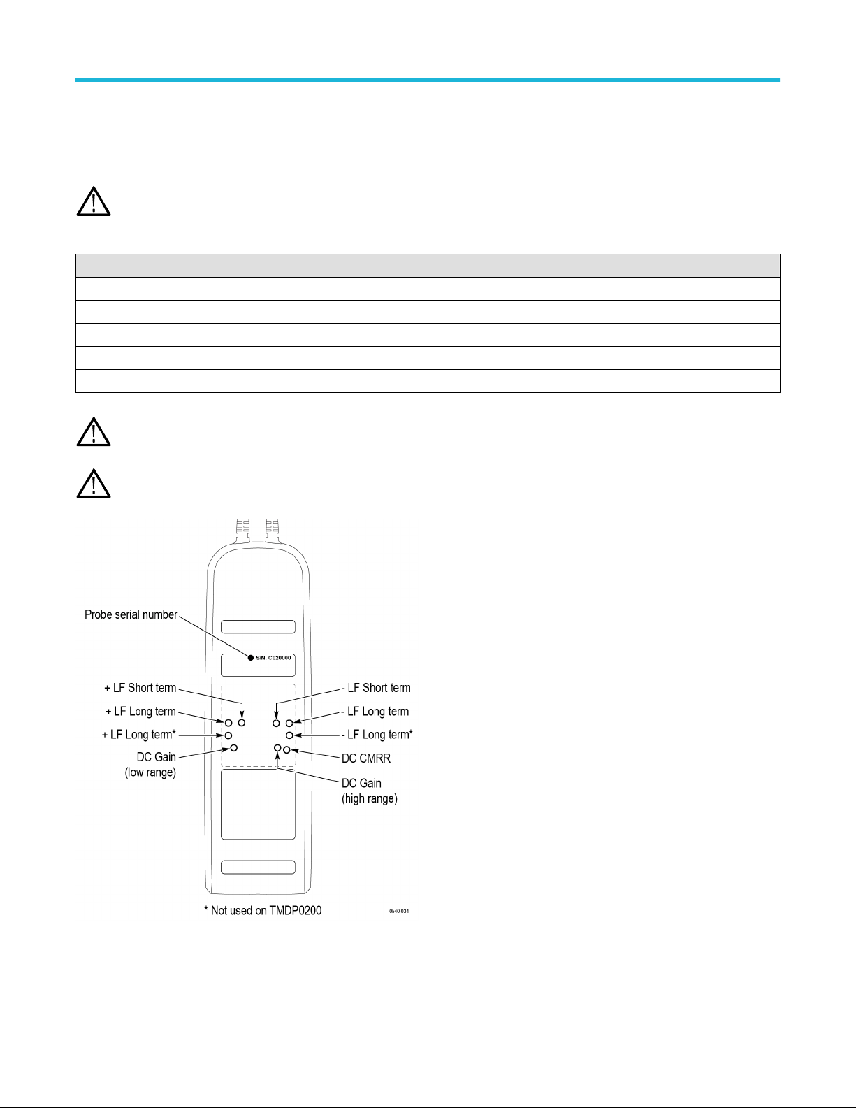
Figure 16: Probe serial number and adjustment locations
Adjustments
High Voltage Differential Probes THDP0100/0200 and TMDP0200 User Manual 51