THDP-TMDP_Instructions-077054003.pdf - 第34页
Replacement Label (Safety Item; Service Only) This reusable label covers the openings to the service-only adjustments on the back of the probe. T o maintain the safety of the probe, the label must be replaced after servi…
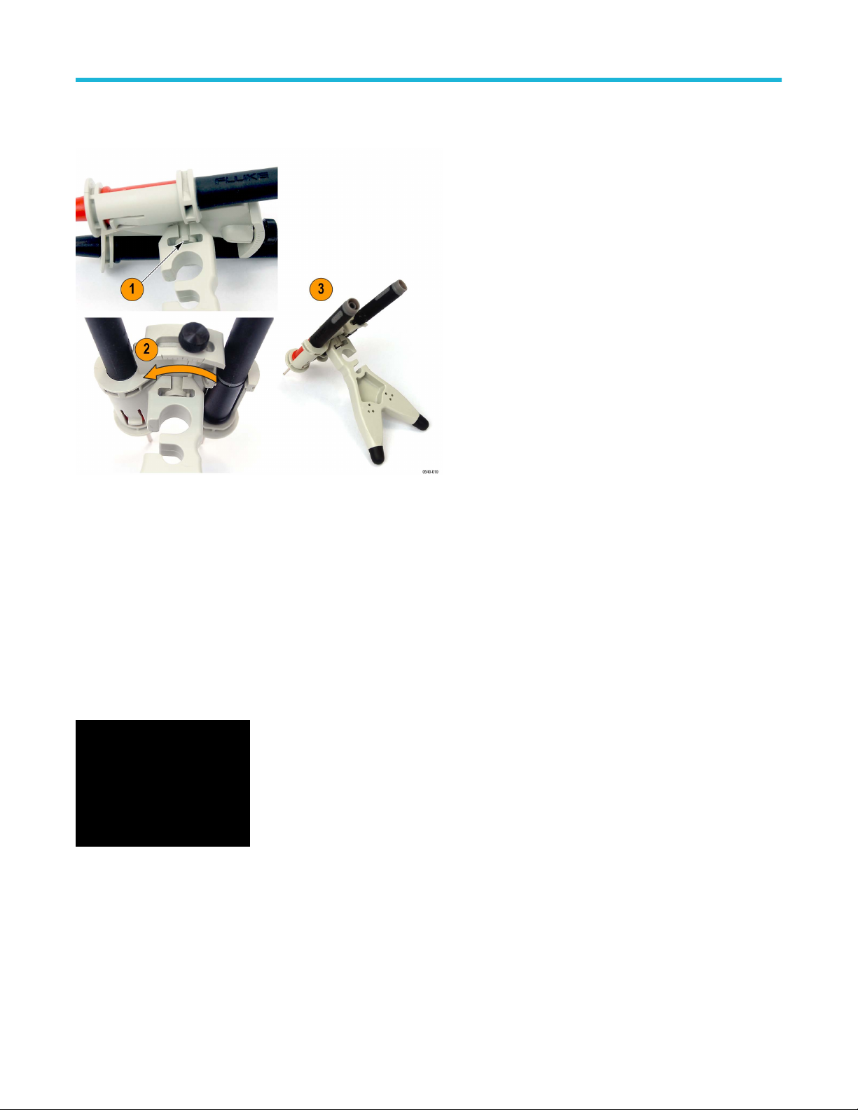
2. Rotate the browser 90°.
3. Position the probe tips on your test points so that you can set the holder on a stable surface.
One THV-Browser is included with the probes.
Reorder T
ektronix part number: THV-Browser
THDP and TMDP Series probes optional accessories
TekVPI Calibration Fixture
This calibration fixture is required to complete a performance verification and adjustment procedures on the probe. It provides power to the
probe and routes the probe output signal through an SMA connector on the back of the fixture.
The signal can then be measured with another instrument, (for example, a precision DMM), to check and adjust probe qualities such as
gain accuracy.
Order Tektronix part number: 067-1701-xx
Accessories and options
High Voltage Differential Probes THDP0100/0200 and TMDP0200 User Manual 33
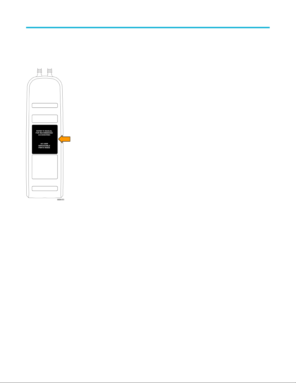
Replacement Label (Safety Item; Service Only)
This reusable label covers the openings to the service-only adjustments on the back of the probe. T
o maintain the safety of the probe, the
label must be replaced after service adjustments are made to the probe.
If the original label becomes damaged or lost, order a replacement label.
Order Tektronix part number: 335-2913-xx
Service Options
Option C3 Calibration Service 3 years
Option C5 Calibration Service 5 years
Option D1 Calibration Data Report
Option D3 Calibration Data Report, 3 years (with Option C3)
Option D5 Calibration Data Report, 5 years (with Option C5)
Option R3 Repair Service 3 years
Option R5 Repair Service 5 years
Accessories and options
34
Operating basics
To help you use the high voltage differential probes safely and effectively, this section provides important information about safety limits,
operating characteristics, and probing techniques.
Operating limits
The probes have two operating ranges that you select with the RANGE button; the ranges differ between probe models.
To keep within the linear measurement region of the probe, select a range that is above the differential voltage that you are measuring. You
can measure a voltage in the low range that exceeds the low range limit (provided it is within the high range limit of the probe), but it will
overdrive the circuitry of the probe. When this differential overrange occurs, the probe detects the condition and lights the OVERRANGE
indicator. Measurements taken in the lower, more sensitive range when the OVERRANGE indicator is lit are not accurate during the
Overdrive Recovery Time (ORT, typically <20 ns, depending on the probe type).
Do not attempt to measure a differential voltage that is above the high operating range of the probe. Do not exceed the common mode
voltage on either input (+ or – input to ground). See Typical characteristics on page 40. The probe can be damaged if these limits are
exceeded.
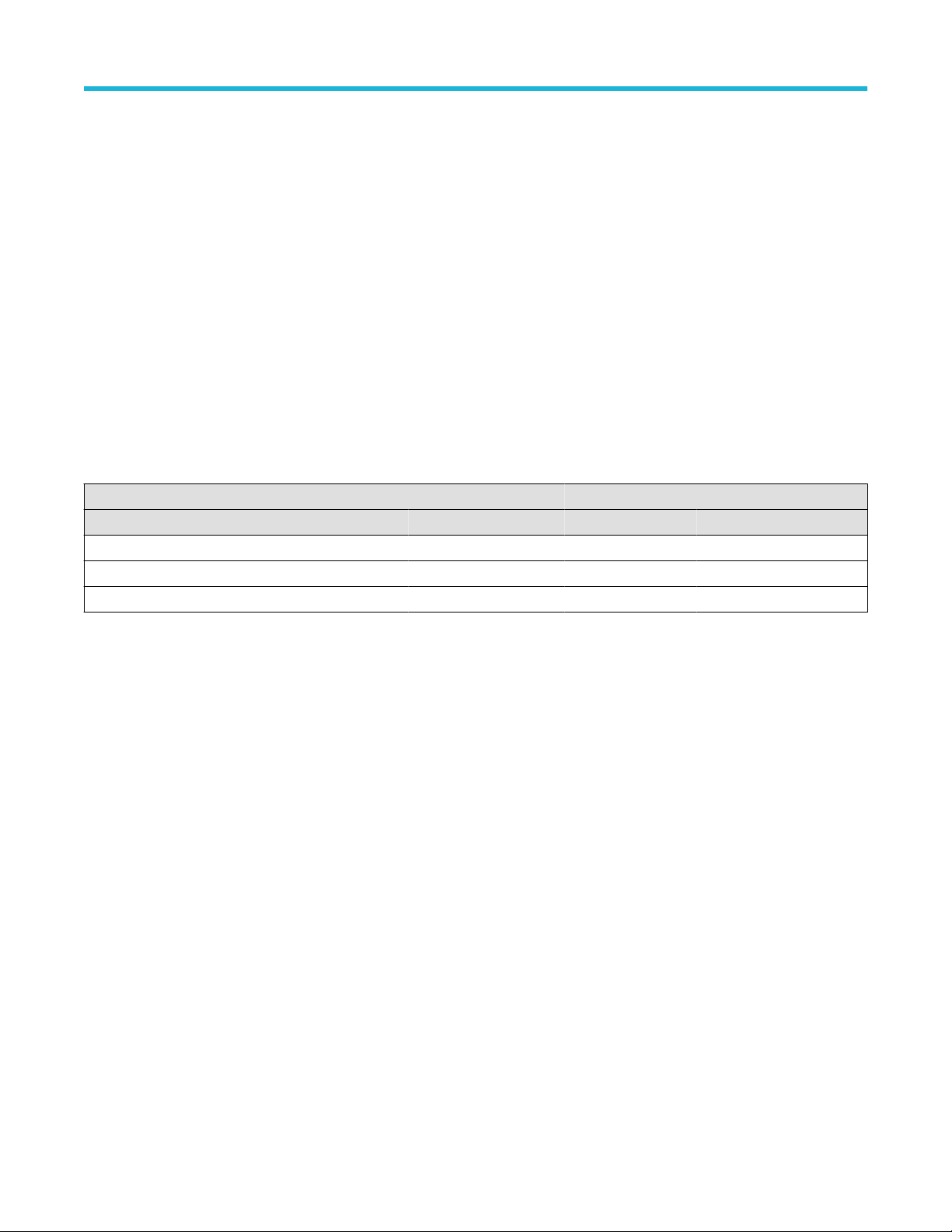
Table 3: Differential voltage limits (peak)
Low range High range
Probe model Voltage limit Overload trip level Voltage limit Overload trip level
THDP0100 600 V >600 V 6000 V >6000 V
THDP0200 150 V >150 V 1500 V >1500 V
TMDP0200 75 V >75 V 750 V >750 V
The input signals that you attempt to measure must be considered both for the differential potential between each other and for the
amplitude on each input with respect to ground (the common mode voltage specification). The maximum common mode voltage limits vary
between probes, from 550 V CA
T I for the TMDP0200, to 2300 V CAT I for the THDP0100 probe. You should consider both specifications
when choosing a probe for your measurement task. Some examples that illustrate this are shown on the following pages.
Operating basics
High Voltage Differential Probes THDP0100/0200 and TMDP0200 User Manual 35