THDP-TMDP_Instructions-077054003.pdf - 第20页
AutoZero The host instrument includes a feature that nulls the DC of fset at the output of the probe. T o initiate the AutoZero routine, do the following: 1. Allow the probe and oscilloscope to warm up for 20 minutes. 2.…
Functional check
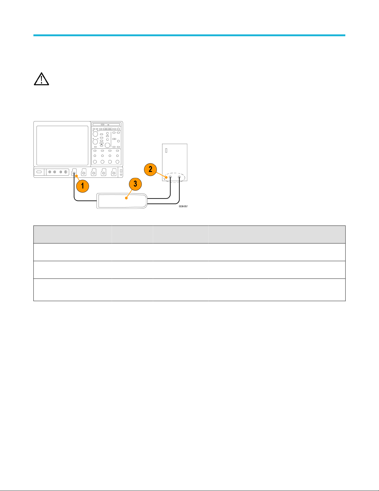
Using accessories that are shipped with your probe and a source that supplies AC line voltage, perform the following procedure:
WARNING: T
o reduce risk of shock or fire, ensure that the accessories are fully mated before you connect to voltage sources
above 42 Vpk.
1. Connect the output of the probe to the oscilloscope input channel.
2. Connect the probe inputs to the AC voltage source.
3. Connect the inputs, set the voltage range, and perform the check as each row of the following table indicates.
Figure 4: Functional check setup
Input 1 (+ or
–)
Input 2 (– or +) Mode Range setting Check
Hot Ground or
Neutral
Differential High (6000 V, 1500 V,
or 750 V)
Measurement instrument displays or indicates the line
voltage
Hot Ground or
Neutral
Differential Low (600 V, 150 V, or
75 V)
Measurement instrument displays or indicates the line
voltage. Overrange indicator lights if the input is ~20% over
Hot Hot (same
connection)
Common Mode High or low
No signal. If a DC offset voltage is present, zero the DC
offset using the AutoZero function.
Probe operating information
High Voltage Differential Probes THDP0100/0200 and TMDP0200 User Manual 19
AutoZero
The host instrument includes a feature that nulls the DC of
fset at the output of the probe. To initiate the AutoZero routine, do the following:
1. Allow the probe and oscilloscope to warm up for 20 minutes.
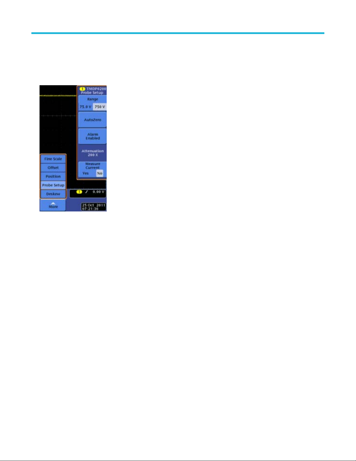
2. Press the MENU button on the probe to display the Probe Setup screen on the oscilloscope.
Figure 5: Probe Setup screen
3. Connect the probe inputs together with the hook tips.
4. Press AutoZero on the Probe Setup screen to initiate the AutoZero routine. If the AutoZero routine does not yield suf
ficient results, use
the DC Offset Zero procedure.
DC offset zero
The offset stored through this feature is retained in the probe between probe power cycles. To set the probe DC offset to 0 V, do the
following:
1. Set the oscilloscope offset for the probe channel to 0 volts.
2. Connect the probe inputs together with the hook tips.
3. Press and hold the probe BANDWIDTH LIMIT and RANGE buttons until the OVERRANGE LED on the probe begins flashing, and then
quickly release the buttons (about 2 seconds).
4. Use the probe BANDWIDTH LIMIT or RANGE buttons to set the probe offset voltage to 0 V, as displayed on the oscilloscope. The
BANDWIDTH LIMIT button decreases the offset voltage and the RANGE button increases it.
5. Press the AUDIBLE OVERRANGE button on the probe to store the value. The OVERRANGE LED on the probe stops flashing to
confirm that the value has been stored.
6. Repeat steps 3 on page 20 through 5 on page 20 for the other range setting on the probe. If you cannot null the offset with these steps,
then use the DC Offset Zero Reset procedure that follows.
Probe operating information
20

DC offset zero reset
T
o reset the probe DC offset to the default values, do the following:
1. Connect the probe inputs together with the hook tips.
2. Press and hold the probe BANDWIDTH LIMIT and RANGE buttons until the OVERRANGE LED on the probe begins flashing.
3. When the OVERRANGE LED remains lit (after about 4 seconds), release the buttons.
4. Press the AUDIBLE OVERRANGE button on the probe to store the value. The OVERRANGE LED on the probe turns off to confirm
that the default value for the DC offset has been stored.
5. Repeat steps 2 on page 21 through 4 on page 21 for the other range setting on the probe.
6. Perform the DC Offset Zero procedure as described in the previous section.
Probe operating information
High Voltage Differential Probes THDP0100/0200 and TMDP0200 User Manual 21