THDP-TMDP_Instructions-077054003.pdf - 第46页
Performance verification Use the following procedures to verify the warranted specifications of the probes. Before beginning these procedures, photocopy the test record and use it to record the performance test results. …
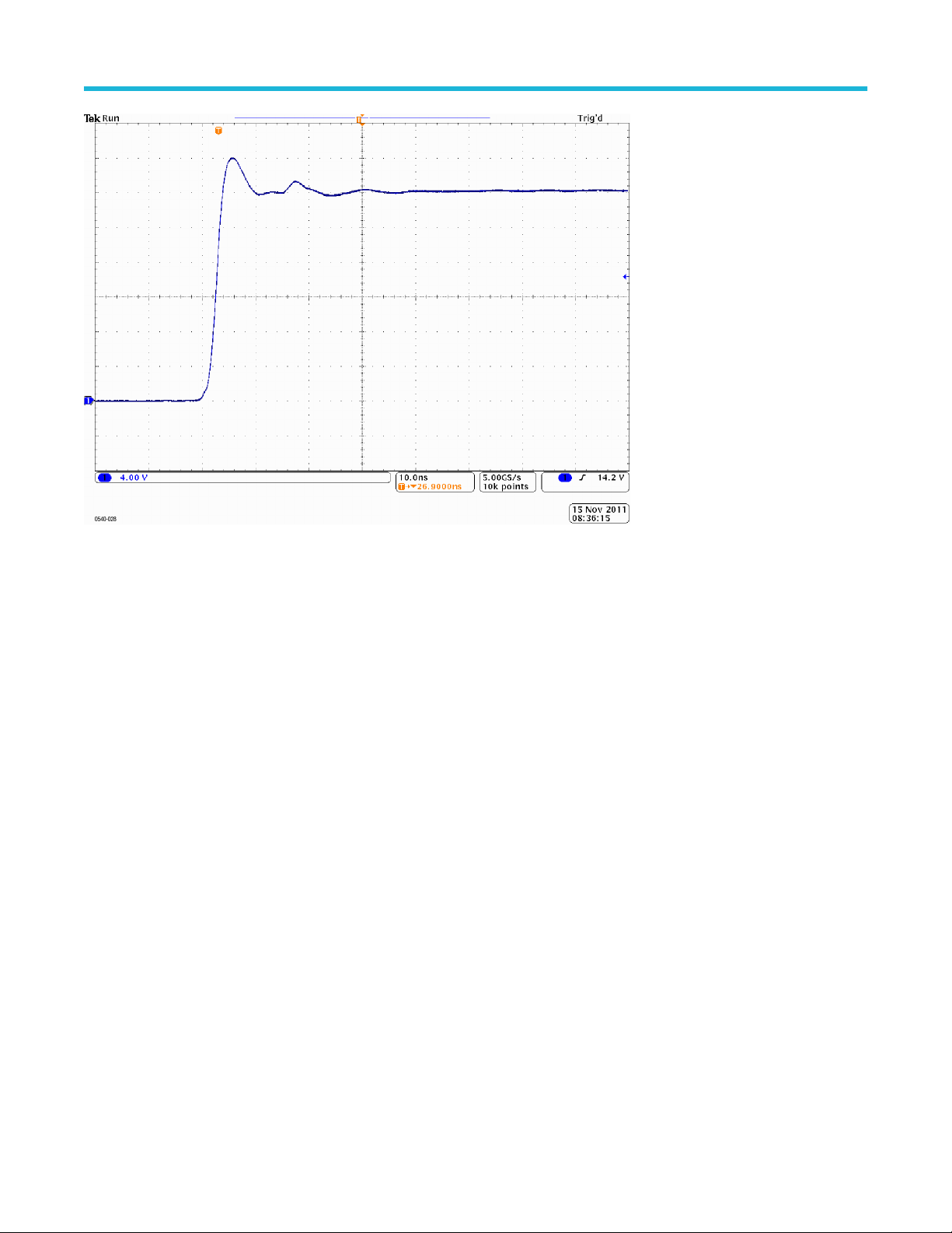
Figure 14: TMDP0200 rise time (typical)
Specifications
High Voltage Differential Probes THDP0100/0200 and TMDP0200 User Manual 45
Performance verification
Use the following procedures to verify the warranted specifications of the probes. Before beginning these procedures, photocopy the test
record and use it to record the performance test results. See Test record on page 50. The recommended calibration interval is one year.
These procedures test the following specifications:
• Gain accuracy
• Rise time
Required equipment
The equipment required to perform the performance verification procedures are shown in the table below. The types and quantities of
connectors may vary depending on the specific equipment you use.
Table 9: Equipment required
Description Minimum requirements Example product
Oscilloscope 500 MHz Tektronix MSO/DSO4000
Generator ±100V variable amplitude, 100 Hz square wave, calibrated Fluke 9100
Pulse generator ≥50 V, 200 ns pulse width, ≤500 ps rise time, 1 kHz Avtech AVR-E2-B-W-P
Probe calibration fixture TekVPI input Tektronix part number 067-1701-xx
Digital Multimeter (DMM) 100 mV and 1 V true RMS AC ranges, <±0.3 % accuracy Tektronix DMM4040/4050
Cable Coax, BNC, 50Ω, 36 in Tektronix part number 012-0482-xx
Adapter BNC female-to-SMA male
Tektronix part number 015-1018-xx
Adapter BNC female-to-dual banana female Tektronix part number 103-0090-xx
Adapter BNC female-to-female Tektronix part number 103-0028-xx
Adapter BNC male-to-dual banana male Fluke PM9081
Termination BNC feedthrough, 50Ω Tektronix part number 011-0049-xx
Attenuator BNC, 50Ω, 2X Tektronix part number 011-0069-xx
Probe hook tips (2) Included with probe accessory kit Tektronix part number AC280–FL
Performance verification
46
TekVPI Calibration Fixture
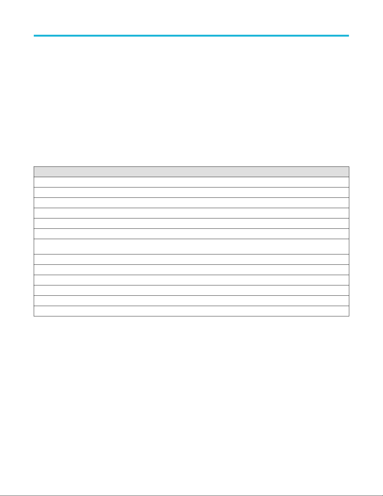
This calibration fixture is required to complete a performance verification and gain accuracy adjustment procedures on the probes. It
provides power to the probe and routes the probe output signal out through an SMA connector on the back of the fixture. The signal can
then be measured with another instrument, such as a precision DMM, to check and adjust the gain accuracy of the probe. Order T
ektronix
part number 067-1701-xx.
Figure 15: TekVPI calibration fixture
T
est procedures
WARNING: These procedures require the application of high voltage to the inputs of the probes. Only qualified personnel
should perform any testing with voltage levels exceeding 30 V
rms
. All pertinent safety rules and guidelines for elevated voltage
measurements should be followed and adhered to.
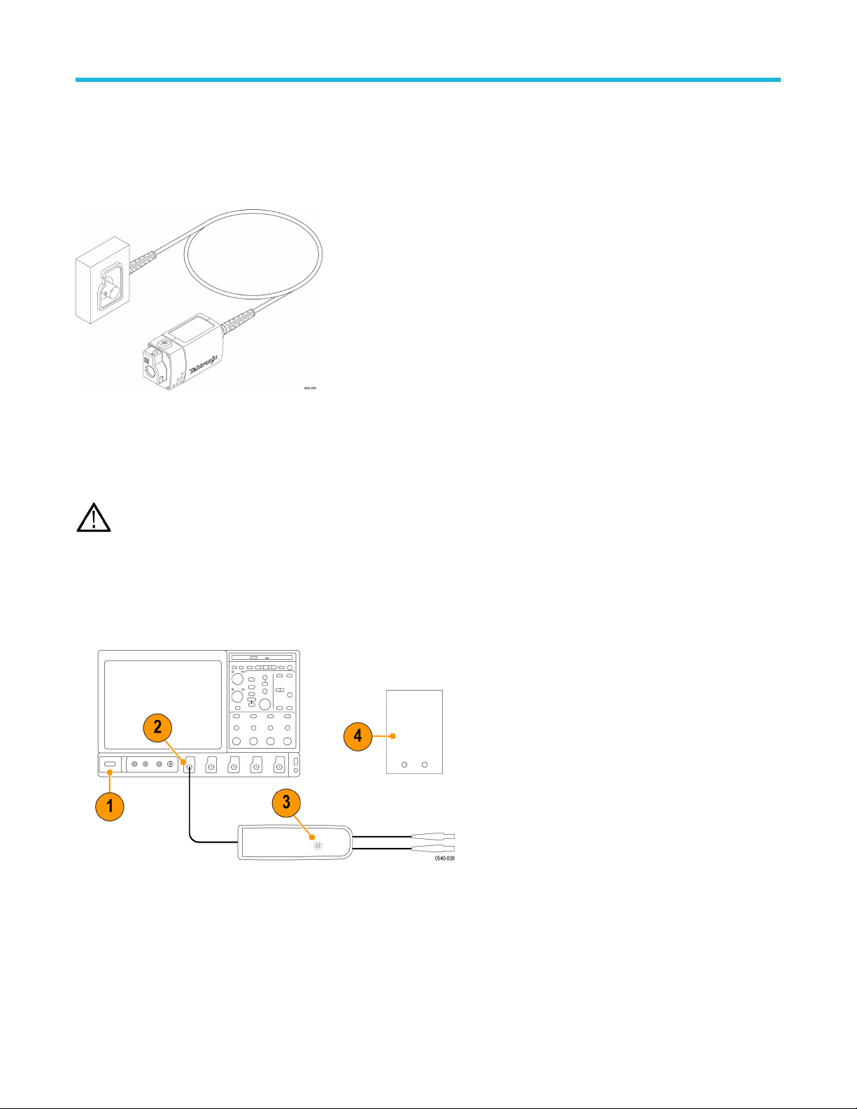
Test setup
1. T
urn on the oscilloscope.
2. Connect the probe to any channel of the oscilloscope.
3. Verify that the LEDs light on the probe.
4. T
urn on the remaining test equipment and let the probe and equipment warm up for 20 minutes.
5. Make a copy of the test record to tabulate the test results. See Test record on page 50.
Performance verification
High Voltage Differential Probes THDP0100/0200 and TMDP0200 User Manual 47