THDP-TMDP_Instructions-077054003.pdf - 第52页
Equipment required The equipment required to perform the adjustment procedures are shown in the table below . The types and quantities of connectors may vary depending on the specific equipment you use. T able 14: Equipm…
Adjustments
Use the following procedures to make adjustments to the THDP and TMDP Series probes. (For probes with serial numbers C019999 and
below, see note and table that follow.) These procedures describe how to make adjustments to the specifications listed below.
Note: Only probes with serial numbers C020000 and above have internal adjustments. Probes with serial numbers C019999 and
below that require adjustments (other than of
fset zero) must be returned to Tektronix for service.
Table 13: THDP and TMDP Series probe adjustments
Specification Adjustment method used Probe serial number
Offset zero External; user probe controls All serial numbers
Gain accuracy Internal; adjustments on PCB Serial numbers C020000 and above
DC CMRR Internal; adjustments on PCB Serial numbers C020000 and above
LF compensation Internal; adjustments on PCB Serial numbers C020000 and above
AC CMRR Internal; adjustments on PCB Serial numbers C020000 and above
Note: The adjustments in the probes are preset at the factory for best overall performance. However
, you may follow these
procedures to check the probe characteristics and optimize them if necessary.
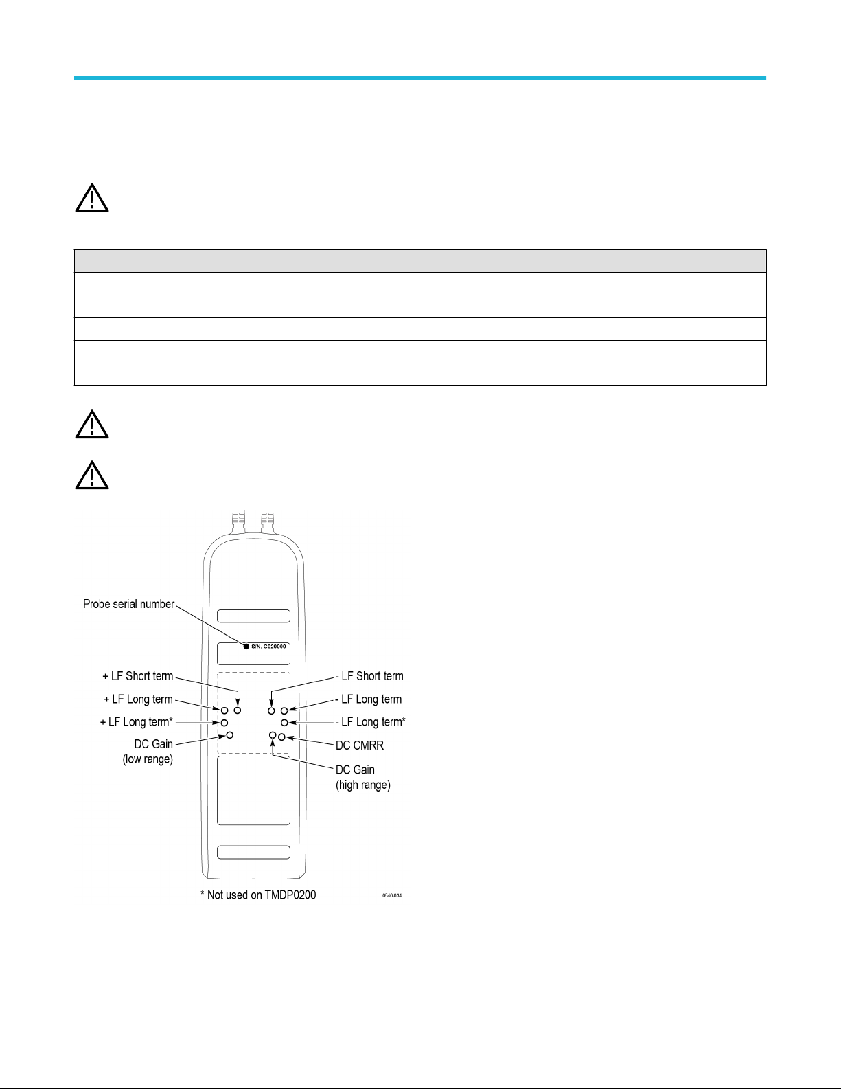
WARNING: These procedures require you to remove a reusable label from the back of the probe. Y
ou must replace the label
after you complete the probe adjustments. Failure to do so may subject the user to high voltages present in the probe during
measurements.
Figure 16: Probe serial number and adjustment locations
Adjustments
High Voltage Differential Probes THDP0100/0200 and TMDP0200 User Manual 51
Equipment required
The equipment required to perform the adjustment procedures are shown in the table below
. The types and quantities of connectors may
vary depending on the specific equipment you use.
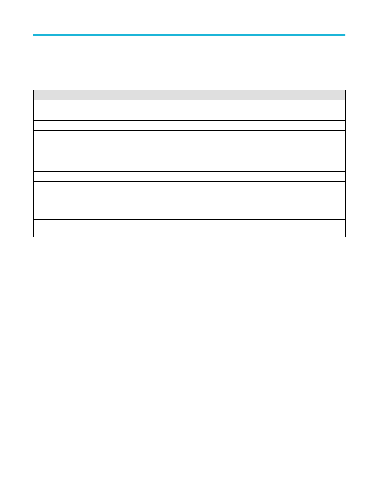
Table 14: Equipment required for adjustments
Description Minimum requirements Example product
Oscilloscope 500 MHz Tektronix MSO/DSO4000
Generator ±100 V variable, 100 Hz square wave, calibrated Fluke 9100
Probe calibration fixture TekVPI inputs Tektronix part number 067-1701-xx
Digital Multimeter (DMM) 100 mV and 1 V true RMS AC ranges, <±0.3 % accuracy Tektronix DMM4040/4050
Cable Coax, BNC, 50 Ω, 36 in Tektronix part number 012-0482-xx
Adapter BNC female-to-SMA male Tektronix part number 015-1018-xx
Adapter BNC male-to-dual binding post Tektronix part number 103-0035-xx
Adapter BNC male-to-dual banana male Fluke PM9081
Probe hook tips (2) Included with probe accessory kit Tektronix part number AC280–FL
Adjustment tool Insulated, slotted (straight) head Tektronix part number 003-1433-xx
Adjustment tool. Required for
the CMRR adjustment.
Insulated, narrow-slotted (straight) head Tektronix part number 003-1928-xx
Replacement rear-panel
label
Reusable, adhesive-backed label that covers adjustment
access openings
Tektronix part number 335-2913-xx
The original label is backed with a reusable adhesive. If the label does not sufficiently adhere to the probe, order a replacement. Label
removal is not required to access of
fset zero adjustments
Adjustments
52
Adjustment procedures
WARNING: These procedures require the application of high voltage to the inputs of the probes. Only qualified personnel
should perform any testing with voltage levels exceeding 30 V
rms
. All pertinent safety rules and guidelines for elevated voltage
measurements should be followed and adhered to.
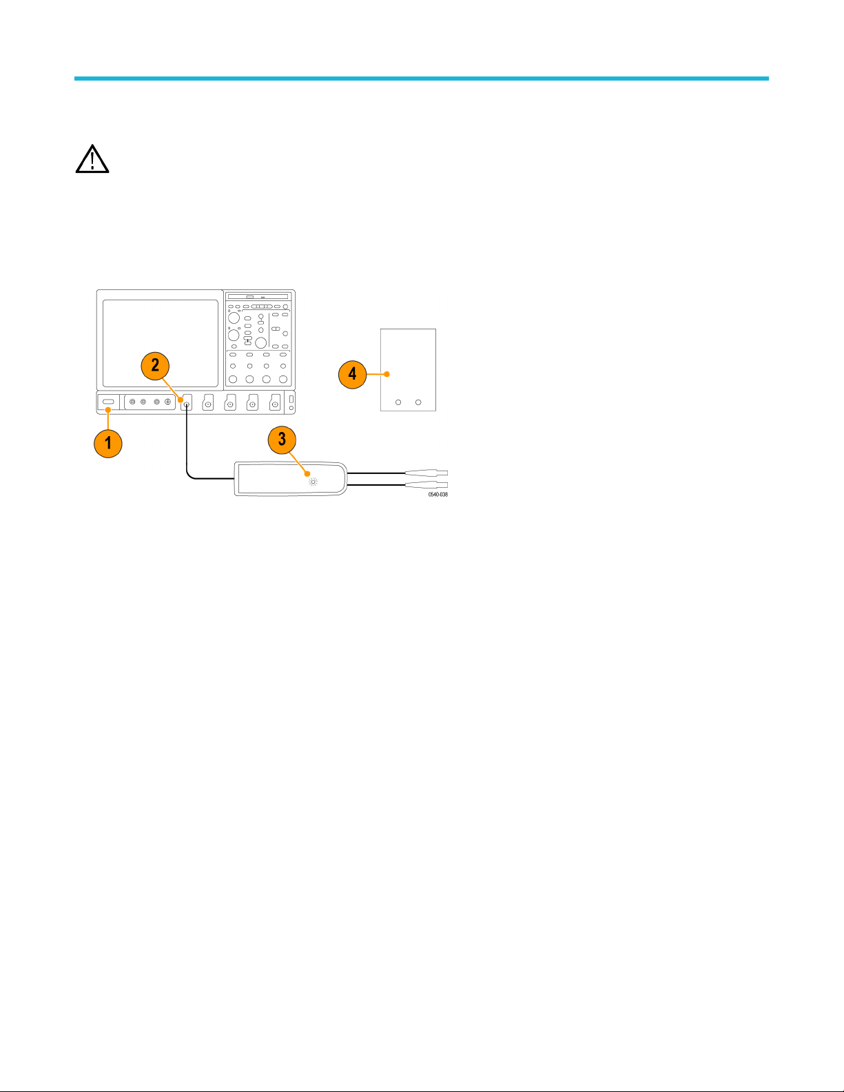
Test setup
1. T
urn on the oscilloscope.
2. Connect the probe to any channel of the oscilloscope.
3. Verify that the LEDs light on the probe.
4. T
urn on the remaining test equipment and let the probe and equipment warm up for 20 minutes.
Adjustments
High Voltage Differential Probes THDP0100/0200 and TMDP0200 User Manual 53