THDP-TMDP_Instructions-077054003.pdf - 第60页
T able 18: AC CMRR test equipment settings Probe Generator output Model Range V oltage (p-p) Frequency THDP0100 600 V 297 V 100 kHz THDP0200 150 V 297 V 100 kHz TMDP0200 75 V 297 V 100 kHz 4. Set the oscilloscope horizon…
Probe Generator output
Model Range Voltage (p-p) Frequency
THDP0200 150 V 50 V 10 kHz
TMDP0200 75 V 50 V 10 kHz
7. Enable the generator output. Set the oscilloscope vertical to display the signal.
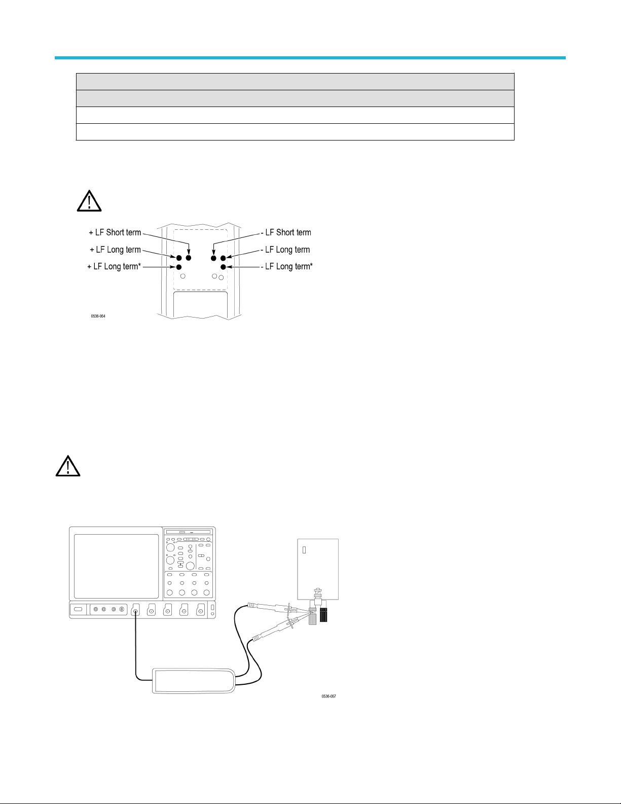
8. Make the adjustments in the following order: long-term +LF
, long-term +LF*, short-term +LF. (The long-term +LF* adjustment is not
used in the TMDP0200 probe.) Repeat this sequence as necessary to optimize the square-wave response.
WARNING: Use only an insulated tool to make the adjustment. Failure to do so presents a potential shock hazard.
9. Disable the generator output.
10. Reverse the probe input leads to the generator
.
11. Invert the signal and trigger slope on the oscilloscope to display the rising edge of the signal. Adjust the trigger level if necessary.
12. Enable the generator output and make the adjustments in the following order: long-term –LF, long-term –LF*, short-term –LF. (The
long-term –LF* adjustment is not used in the TMDP0200 probe.) Repeat this sequence as necessary to optimize the square-wave
response.
AC CMRR
WARNING: Dangerous voltages will be present on the calibration generator output terminals and connection cables. Always verify
that the generator is in the standby mode before you make any connections to the generator
.
1. V
erify that the generator output is off.
2. Connect both of the probe inputs to the red (+) banana connector on the front output of the generator. Use a BNC-banana adapter if
necessary.
3. Set the output of the generator to 297 V
p-p
(105 V
rms) @100 kHz.
Adjustments
High Voltage Differential Probes THDP0100/0200 and TMDP0200 User Manual 59
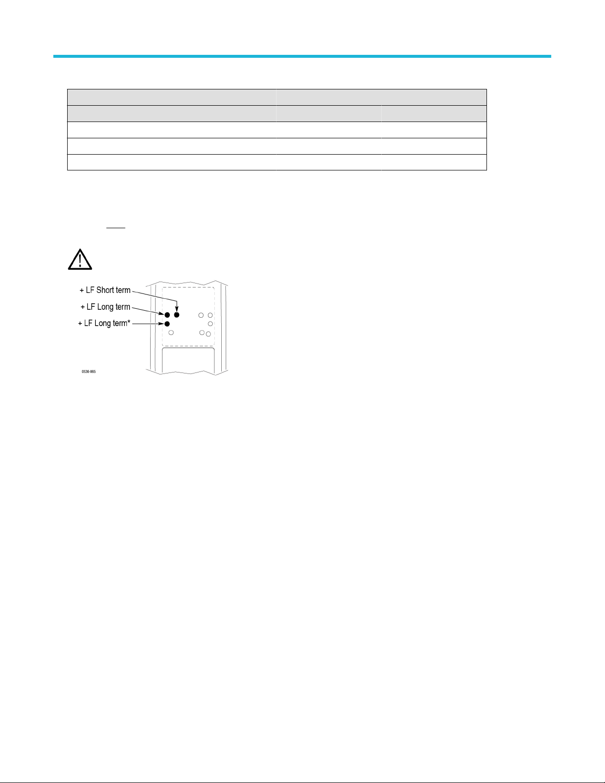
Table 18: AC CMRR test equipment settings
Probe Generator output
Model Range Voltage (p-p) Frequency
THDP0100 600 V 297 V 100 kHz
THDP0200 150 V 297 V 100 kHz
TMDP0200 75 V 297 V 100 kHz
4. Set the oscilloscope horizontal to 10
μs/div.
5. Set the probe bandwidth to full and the attenuation to the lower range of the probe.
6. Enable the generator output. Adjust the oscilloscope vertical to display the signal.
7. Make only
slight adjustments to only the +LF pots to optimize the CMRR (minimize the signal amplitude). Adjust the pots in the
following order: short-term +LF
, long-term +LF, long-term +LF*. (The long-term +LF* adjustment is not used in the TMDP0200 probe.)
WARNING: Use only an insulated tool to make the adjustment. Failure to do so presents a potential shock hazard.
This completes the adjustment procedures.
Adjustments
60

Maintenance
Information to isolate possible failures and procedures for maintaining your probe.
Host instrument firmware
Some instruments may require a firmware upgrade to support full functionality of the latest probes that are offered by Tektronix.
Instruments with lower versions of firmware may not display all probe controls and indicators on screen, and in some cases may require
you to power-cycle the instrument to restore normal instrument operation. If you are having problems with your probe and suspect that you
need to upgrade your instrument firmware, go to www.tektronix.com/probe-support to download the latest firmware.
To check the firmware version on Windows-based instruments, from the menu bar, click Help/About TekScope. On Linux-based
instruments, press the Utilities button on the front panel.
Error conditions
LEDs do not remain lit
If none of the LEDs remain lit after you connect the probe, a probe/oscilloscope interface fault may exist. Perform the following steps until
you clear the fault or isolate the problem:
• Disconnect and reconnect the probe to restart the power-on diagnostic sequence.
• Connect the probe to a different channel on the oscilloscope.
• Disconnect the probe from the oscilloscope, power-cycle the oscilloscope, and then reconnect the probe.
• Connect the probe to a different oscilloscope.
If the symptoms remain (they follow the probe), then the probe is defective and must be returned to Tektronix for repair.
Signal display
If the probe is connected to an active signal source and you do not see the signal displayed on the oscilloscope:
• Check that the probe accessories that you are using are fully mated.
• Check the probe connection on your circuit.
• Perform a functional check on the probe.
Cleaning
Protect the probe from adverse weather conditions. The probe is not waterproof.
CAUTION: T
o prevent damage to the probe, do not expose it to sprays, liquids, or solvents. Avoid getting moisture inside the
probe when cleaning the exterior.
Clean the exterior surfaces of the probe with a dry, lint-free cloth or a soft-bristle brush. If dirt remains, use a soft cloth or swab dampened
with a 75% isopropyl alcohol solution. Use only enough solution to dampen the cloth or swab. Do not use abrasive compounds on any part
of the probe.
Maintenance
High Voltage Differential Probes THDP0100/0200 and TMDP0200 User Manual 61