THDP-TMDP_Instructions-077054003.pdf - 第36页
Measurement examples Example 1 Consider a case where you need to measure two sinusoidal waveforms that are 180° out of phase with each other , each with an amplitude of 1000 V pk with no DC offset (centered at 0 V). Figu…

Operating basics
To help you use the high voltage differential probes safely and effectively, this section provides important information about safety limits,
operating characteristics, and probing techniques.
Operating limits
The probes have two operating ranges that you select with the RANGE button; the ranges differ between probe models.
To keep within the linear measurement region of the probe, select a range that is above the differential voltage that you are measuring. You
can measure a voltage in the low range that exceeds the low range limit (provided it is within the high range limit of the probe), but it will
overdrive the circuitry of the probe. When this differential overrange occurs, the probe detects the condition and lights the OVERRANGE
indicator. Measurements taken in the lower, more sensitive range when the OVERRANGE indicator is lit are not accurate during the
Overdrive Recovery Time (ORT, typically <20 ns, depending on the probe type).
Do not attempt to measure a differential voltage that is above the high operating range of the probe. Do not exceed the common mode
voltage on either input (+ or – input to ground). See Typical characteristics on page 40. The probe can be damaged if these limits are
exceeded.
Table 3: Differential voltage limits (peak)
Low range High range
Probe model Voltage limit Overload trip level Voltage limit Overload trip level
THDP0100 600 V >600 V 6000 V >6000 V
THDP0200 150 V >150 V 1500 V >1500 V
TMDP0200 75 V >75 V 750 V >750 V
The input signals that you attempt to measure must be considered both for the differential potential between each other and for the
amplitude on each input with respect to ground (the common mode voltage specification). The maximum common mode voltage limits vary
between probes, from 550 V CA
T I for the TMDP0200, to 2300 V CAT I for the THDP0100 probe. You should consider both specifications
when choosing a probe for your measurement task. Some examples that illustrate this are shown on the following pages.
Operating basics
High Voltage Differential Probes THDP0100/0200 and TMDP0200 User Manual 35
Measurement examples
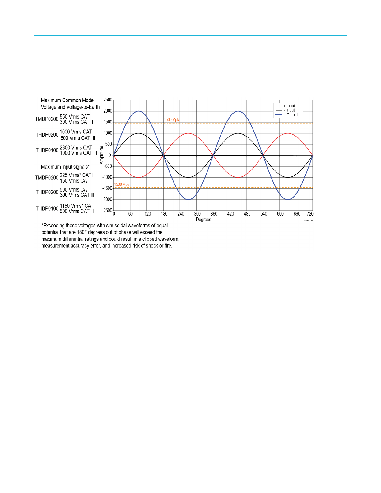
Example 1
Consider a case where you need to measure two sinusoidal waveforms that are 180° out of phase with each other
, each with an amplitude
of 1000 V
pk
with no DC offset (centered at 0 V).
Figure 6: Measuring two equal-amplitude waveforms that are 180 degrees out of phase
If both waveforms are at the same voltage potential, then the dif
ferential measurement would be 2 times the individual signal inputs (in
this example, 2000 V
pk
). Looking at the maximum measurable differential voltage specifications for the THDP/TMDP series probes, the
THDP0100 probe is capable of measuring this signal. See Typical characteristics on page 40. For reference, the rms values of the
Common-Mode Voltage and Voltage-to-Earth ratings and Maximum Input Signals for each probe model are shown in the figure above.
Operating basics
36
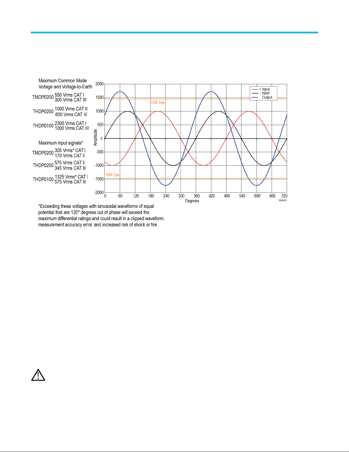
Example 2
Next, assume that the same waveforms from the previous example are 120° out of phase with each other
. This phase relationship yields a
maximum differential of 1.732 times the individual signal inputs, or 1732 V
pk
. Although this is a lower potential between the inputs than in
example 1, it exceeds the differential voltage ratings of the THDP0200 and TMDP0200 probes, so you must use the THDP0100 probe.
Figure 7: Measuring two equal-amplitude waveforms that are 120 degrees out of phase
Example 3
Y
our task is to measure two AC waveforms of the same phase, each with an amplitude of 300 V. However, one waveform is centered
on ground (– input), and the other is centered on an offset of 400 VDC (+ input). The common mode voltage is the 300 V
rms
, but the
maximum voltage-to-earth (the common mode voltage plus the signal waveform) must also be taken into account for both inputs. The
voltage-to-earth is 300 V
rms
on the (– input), but on the (+ input), the voltage-to-earth is 700 V
rms
(the 300 VAC
rms
plus the 400 VDC
rms
).
Thus the (+ input) exceeds the maximum input voltage-to-earth rating of the THDP0200 probe, so it cannot be used for taking this
measurement. In this case, you must use either the TMDP0200 or THDP0100 probe.
Overrange detection
Differential voltage outside the operating range will overdrive the circuitry of the probe and distort the output signal. When this differential
overrange occurs, the probe detects the condition and lights the overrange indicator. With the Audible Overrange ON, the probe will also
emit an audible alarm.
WARNING: The Overrange indicator does not detect an overrange condition of common-mode voltages or voltage-to-earth
potential at the probe inputs. The Overrange indicator only detects dif
ferentially between the + and – inputs (not relative to
ground). Do not exceed the Common-Mode Voltage or Input Voltage-to-Earth ratings of the probe when taking measurements.
If you are not sure, first take a single-ended measurement of each point that you are intending to measure differentially. Take a
single-ended measurement by tying one input lead to ground (the – input) and then connecting the other lead (the + input) to the
points of interest, one at a time.
Operating basics
High Voltage Differential Probes THDP0100/0200 and TMDP0200 User Manual 37