THDP-TMDP_Instructions-077054003.pdf - 第38页
Common-mode rejection The common-mode rejection ratio (CMRR) is the specified ability of a probe to reject signals that are common to both inputs. More precisely , CMRR is the ratio of the differential gain to the common…
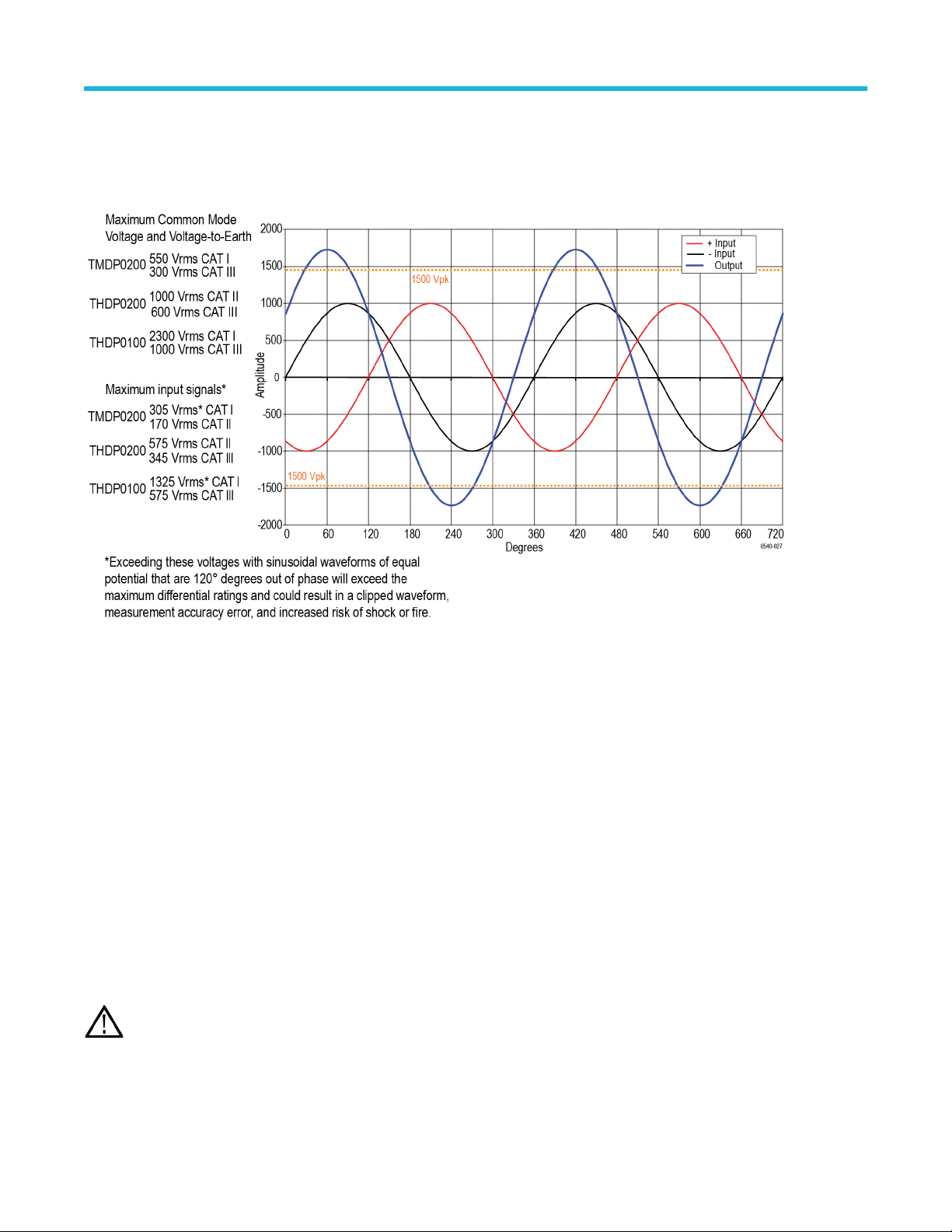
Example 2
Next, assume that the same waveforms from the previous example are 120° out of phase with each other
. This phase relationship yields a
maximum differential of 1.732 times the individual signal inputs, or 1732 V
pk
. Although this is a lower potential between the inputs than in
example 1, it exceeds the differential voltage ratings of the THDP0200 and TMDP0200 probes, so you must use the THDP0100 probe.
Figure 7: Measuring two equal-amplitude waveforms that are 120 degrees out of phase
Example 3
Y
our task is to measure two AC waveforms of the same phase, each with an amplitude of 300 V. However, one waveform is centered
on ground (– input), and the other is centered on an offset of 400 VDC (+ input). The common mode voltage is the 300 V
rms
, but the
maximum voltage-to-earth (the common mode voltage plus the signal waveform) must also be taken into account for both inputs. The
voltage-to-earth is 300 V
rms
on the (– input), but on the (+ input), the voltage-to-earth is 700 V
rms
(the 300 VAC
rms
plus the 400 VDC
rms
).
Thus the (+ input) exceeds the maximum input voltage-to-earth rating of the THDP0200 probe, so it cannot be used for taking this
measurement. In this case, you must use either the TMDP0200 or THDP0100 probe.
Overrange detection
Differential voltage outside the operating range will overdrive the circuitry of the probe and distort the output signal. When this differential
overrange occurs, the probe detects the condition and lights the overrange indicator. With the Audible Overrange ON, the probe will also
emit an audible alarm.
WARNING: The Overrange indicator does not detect an overrange condition of common-mode voltages or voltage-to-earth
potential at the probe inputs. The Overrange indicator only detects dif
ferentially between the + and – inputs (not relative to
ground). Do not exceed the Common-Mode Voltage or Input Voltage-to-Earth ratings of the probe when taking measurements.
If you are not sure, first take a single-ended measurement of each point that you are intending to measure differentially. Take a
single-ended measurement by tying one input lead to ground (the – input) and then connecting the other lead (the + input) to the
points of interest, one at a time.
Operating basics
High Voltage Differential Probes THDP0100/0200 and TMDP0200 User Manual 37

Common-mode rejection
The common-mode rejection ratio (CMRR) is the specified ability of a probe to reject signals that are common to both inputs. More
precisely
, CMRR is the ratio of the differential gain to the common-mode gain. The higher the ratio, the greater the ability of probe to reject
common-mode signals.
Common mode rejection decreases as the input frequency increases. For example, if you apply a 60 Hz line voltage of 500 V
p-p
to
both input leads of the probe, the probe rejects the signal by 80 dB (typical) and the signal appears as only a 50 mV
p-p
signal on the
oscilloscope screen.
Twisting the input leads
Twisting the input leads helps to cancel noise from high-EMI environments that is induced into the input leads.
Probe Loading
When you touch your probe tip to a circuit element, you are introducing a new resistance, capacitance, and inductance into the circuit.
Frequency and impedance of the source determine how much the probe loads the circuit you are measuring. As the frequency of the
source starts to increase beyond 1 kHz, the input impedance of the probe begins to decrease.
The lower the impedance of the probe relative to that of the source, the more the probe loads the circuit under test. For a graph of
frequency versus input impedance, refer to the Specifications section. As the graph shows, the probes have virtually no loading ef
fect on
sources with relatively low impedance and low frequency.
Operating basics
38
Specifications
The specifications shown apply to the THDP/TMDP series probes installed on Tektronix MSO/DSO4000 oscilloscopes. When a probe is
used with another oscilloscope, the oscilloscope must have an input impedance of 1 MΩ and a bandwidth equal to or greater than the
probe. The probe must have a warm-up period of at least 20 minutes and be in an environment that does not exceed the limits described.
See Table 5 on page 39. Specifications for the THDP/TMDP series probes fall into three categories: warranted, typical and nominal
characteristics.
Warranted specifications
Warranted characteristics describe guaranteed performance within tolerance limits or certain type-tested requirements.
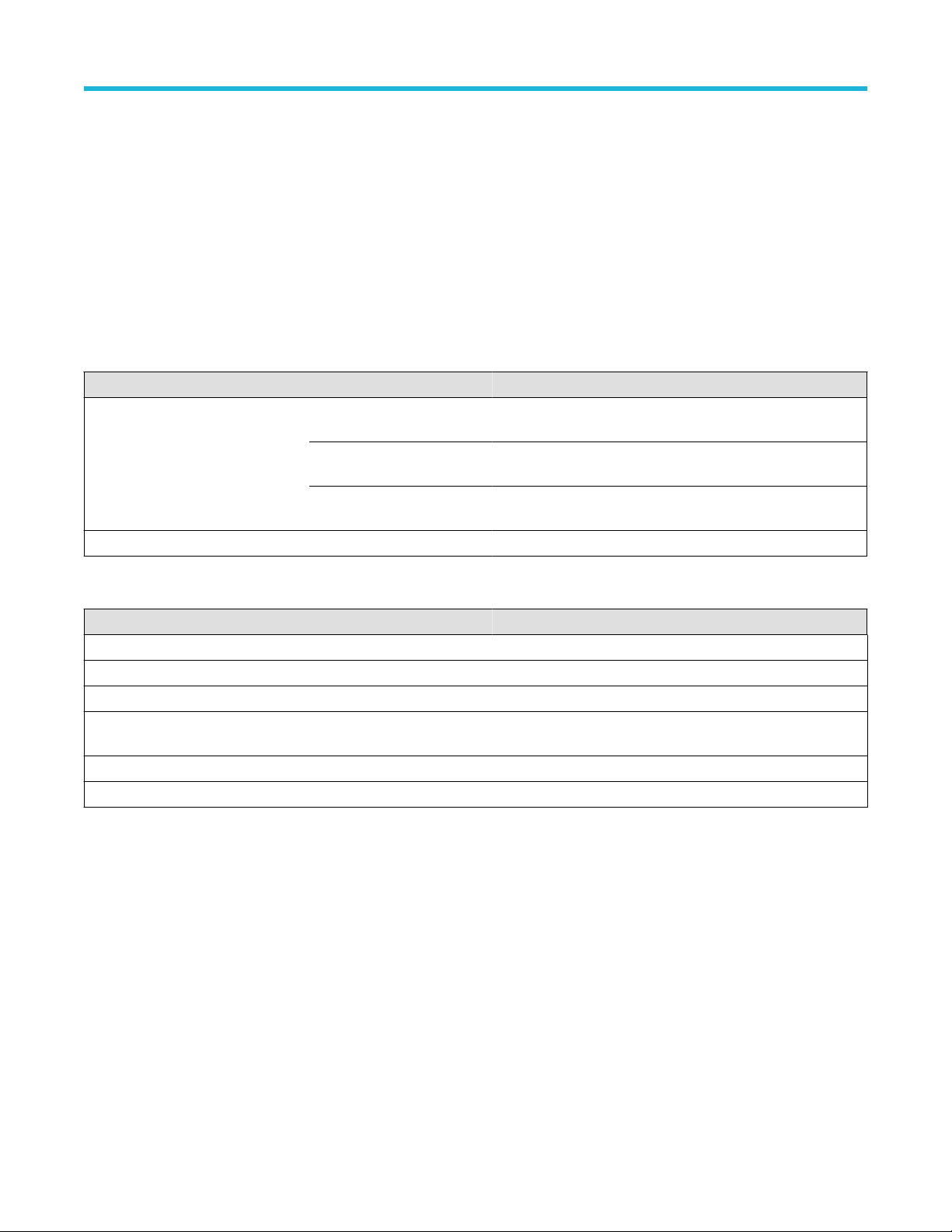
Table 4: Warranted electrical specifications
Characteristics THDP0100 THDP0200 TMDP0200
Rise time (small signal, 10–90%,
+20 °C to +30 °C). Output may be
slew rate limited for large amplitude
signals.
600 V: ≤3.6 ns(typical:
≤3.5 ns)
150 V: ≤2.4 ns(typical: ≤2.2 ns) 75 V: ≤2.4 ns(typical: ≤2.2 ns)
6000 V: ≤3.6 ns(typical:
≤3.5 ns)
1500 V: ≤2.0 ns(typical:
≤1.8 ns)
750 V: ≤2.0 ns(typical: ≤1.8 ns)
(slew rate ≥2500 V/ns
(6000 V))
(slew rate ≥650 V/ns (1500 V)) (slew rate ≥275 V/ns (750 V))
DC gain accuracy ±2% ±2% ±2%
Table 5: Warranted environmental specifications
Characteristics THDP0100 THDP0200 TMDP0200
Operating Temperature 0 °C to 40 °C (32 °F to +104 °F)
Nonoperating Temperature –30° C to +70° C (–22 °F to +158 °F)
Operating Humidity 5 to 85% RH (Relative Humidity) 0 °C to +40 °C (32 °F to +104 °F)
Nonoperating Humidity 5% to 85% RH at up to +40° C (+104 °F). 5% to 45% RH above +40° C up to +70° C (+104 to
+158 °F)
Operating Altitude 3,000 m (9,842 ft)
Nonoperating Altitude 15,240 m (50,000 ft)
Specifications
High Voltage Differential Probes THDP0100/0200 and TMDP0200 User Manual 39