THDP-TMDP_Instructions-077054003.pdf - 第40页
T ypical characteristics T ypical characteristics describe typical but not guaranteed performance. T able 6: T ypical electrical characteristics Characteristics THDP0100 THDP0200 TMDP0200 Maximum measurable differential …

Specifications
The specifications shown apply to the THDP/TMDP series probes installed on Tektronix MSO/DSO4000 oscilloscopes. When a probe is
used with another oscilloscope, the oscilloscope must have an input impedance of 1 MΩ and a bandwidth equal to or greater than the
probe. The probe must have a warm-up period of at least 20 minutes and be in an environment that does not exceed the limits described.
See Table 5 on page 39. Specifications for the THDP/TMDP series probes fall into three categories: warranted, typical and nominal
characteristics.
Warranted specifications
Warranted characteristics describe guaranteed performance within tolerance limits or certain type-tested requirements.
Table 4: Warranted electrical specifications
Characteristics THDP0100 THDP0200 TMDP0200
Rise time (small signal, 10–90%,
+20 °C to +30 °C). Output may be
slew rate limited for large amplitude
signals.
600 V: ≤3.6 ns(typical:
≤3.5 ns)
150 V: ≤2.4 ns(typical: ≤2.2 ns) 75 V: ≤2.4 ns(typical: ≤2.2 ns)
6000 V: ≤3.6 ns(typical:
≤3.5 ns)
1500 V: ≤2.0 ns(typical:
≤1.8 ns)
750 V: ≤2.0 ns(typical: ≤1.8 ns)
(slew rate ≥2500 V/ns
(6000 V))
(slew rate ≥650 V/ns (1500 V)) (slew rate ≥275 V/ns (750 V))
DC gain accuracy ±2% ±2% ±2%
Table 5: Warranted environmental specifications
Characteristics THDP0100 THDP0200 TMDP0200
Operating Temperature 0 °C to 40 °C (32 °F to +104 °F)
Nonoperating Temperature –30° C to +70° C (–22 °F to +158 °F)
Operating Humidity 5 to 85% RH (Relative Humidity) 0 °C to +40 °C (32 °F to +104 °F)
Nonoperating Humidity 5% to 85% RH at up to +40° C (+104 °F). 5% to 45% RH above +40° C up to +70° C (+104 to
+158 °F)
Operating Altitude 3,000 m (9,842 ft)
Nonoperating Altitude 15,240 m (50,000 ft)
Specifications
High Voltage Differential Probes THDP0100/0200 and TMDP0200 User Manual 39
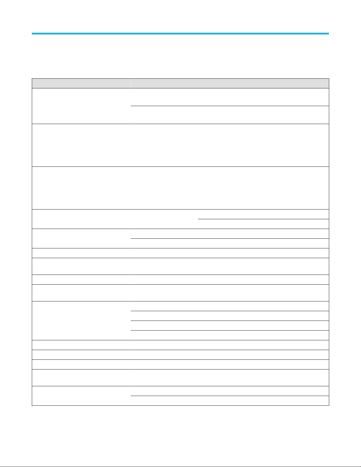
Typical characteristics
T
ypical characteristics describe typical but not guaranteed performance.
Table 6: Typical electrical characteristics
Characteristics THDP0100 THDP0200 TMDP0200
Maximum measurable differential voltage.
This is the maximum measurable range of
the probe. Beyond these limits, the output
could be clipped.
600 V Range: 600 V DC +
peak AC, 450 V
rms
150 V Range: 150 V DC +
peak AC, 100 V
rms
75 V Range: 75 V DC +
peak AC, 50 V
rms
6000 V Range: 6000 V DC +
peak AC, 3000 V
rms
1500 V Range: 1500 V DC +
peak AC, 1000 V
rms
750 V Range: 750 V DC +
peak AC, 500 V
rms
Maximum common mode voltage and input
voltage-to-earth. The Common Mode ratings
are the same as the input voltage-to-earth
ratings (the maximum amount that each
input lead (+/-) can be from ground).
±6000 V DC + peak AC,
2300 V CA
T I, 1000 V CAT
III
±1500 V DC + peak AC,
1000 V CAT II, 600 V CAT
III
±750 V DC + peak AC,
550 V CAT I, 300 V CAT III
CAT I Maximum Rated Over- Voltage
Transient (OVT). Applies to CAT I ratings
only (both ranges). The OVT peak is
typically measured on top of the Peak
Working Voltage.
4600 V
pk
NA 3220 V
pk
Bandwidth (-3 dB) DC to ≥100 MHz 150 V: DC to ≥160 MHz 75 V: DC to ≥160 MHz
1500 V: DC to ≥200 MHz 750 V: DC to ≥200 MHz
Offset zero (+20 °C to +30 °C) 600 V: ±1 V 150 V: ±500 mV 75 V: ±200 mV
6000 V: ±10 V 1500 V: ±5 V 750 V: ±2 V
Input resistance between inputs 40 MΩ ±2% 10 MΩ ±2% 5 MΩ ±2%
Input resistance between each input and
ground
20 MΩ ±2% 5 MΩ ±2% 2.5 MΩ ±2%
Input capacitance between inputs <2.5 pF <2.0 pF <2.0 pF
Input capacitance between each input and
ground
<5.0 pF per side <4.0 pF per side <4.0 pF per side
Common Mode Rejection Ratio (20–30°C) DC: >80 dB DC: >80 dB DC: >80 dB
100 kHz: >60 dB 100 kHz: >60 dB 100 kHz: >60 dB
3.2 MHz: >30 dB 3.2 MHz: >30 dB 3.2 MHz: >30 dB
100 MHz: >26 dB 100 MHz: >26 dB 100 MHz: >26 dB
Propagation delay 16 ns 14 ns 14 ns
DC offset drift (output referred) 50 μV/ °C 50 μV/ °C 50 μV/ °C
Bandwidth limit filters 5 MHz 5 MHz 5 MHz
Input overdrive recovery 600 V: <30 ns to 10% of final
value after 5X overdrive
150 V: <20 ns to 10% of final
value after 5X overdrive
75 V: <20 ns to 10% of final
value after 5X overdrive
Input referred noise (mV
rms
) 600 V: <175 mV 150 V: <50 mV 75 V: <25 mV
6000 V: <400 mV 1500 V: <140 mV 750 V: <65 mV
Specifications
40
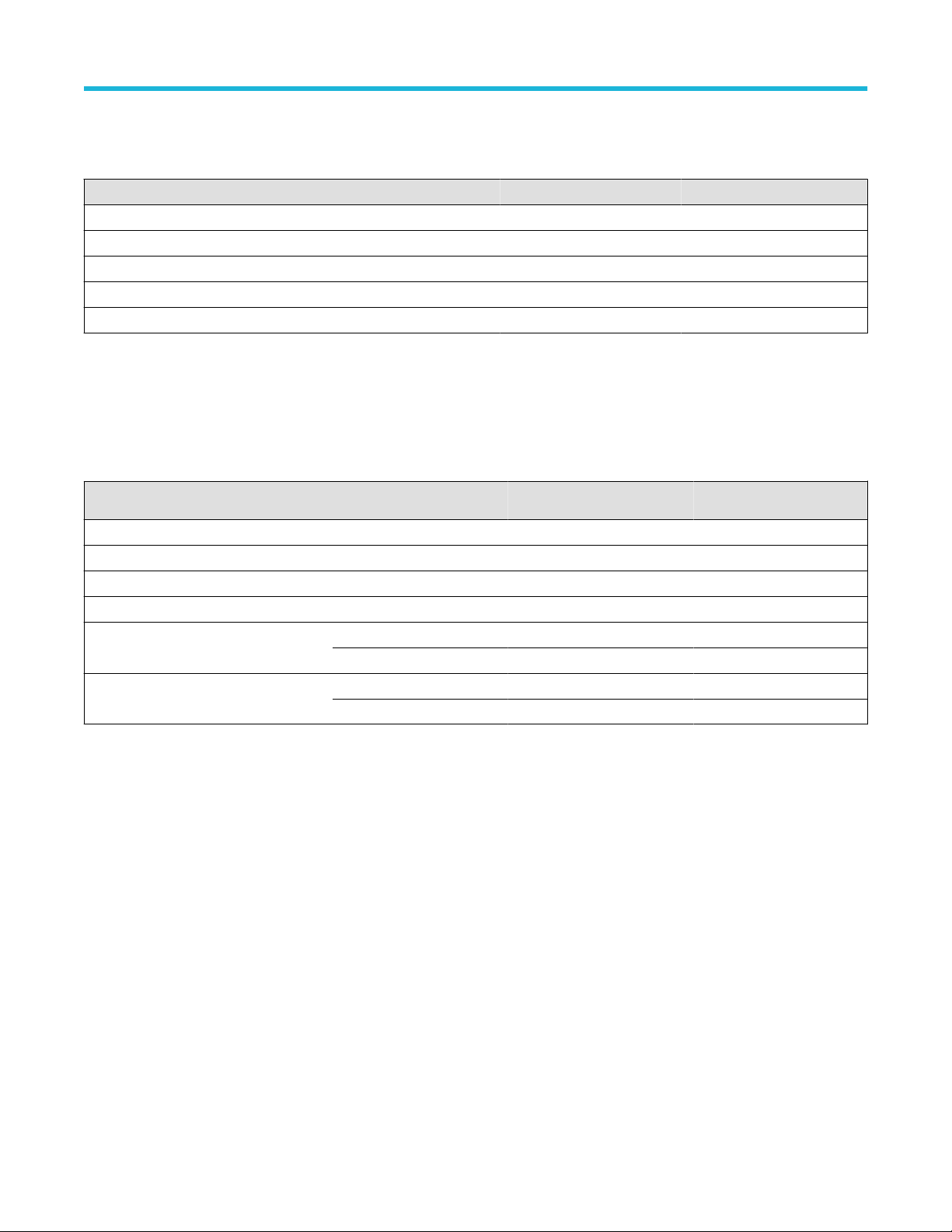
Mechanical characteristics
Table 7: Typical mechanical characteristics
Characteristic THDP0100 THDP0200 TMDP0200
Probe body dimensions 185 mm x 56 mm x 25 mm (7.3 in x 2.2 in x 1.0 in)
Probe control box dimensions 76 mm x 31 mm x 41 mm (3.0 in x 1.2 in x 1.6 in)
Input cable length 25.4 cm (10 in)
Output cable length 1.5 m (59 in)
Weight (probe only) 340 gm (12.0 oz) 309 gm (10.9 oz) 309 gm (10.9 oz)
Nominal characteristics
Nominal characteristics describe guaranteed traits, but the traits do not have tolerance limits.
Table 8: Nominal electrical characteristics
Characteristics THDP0100 THDP0200 TMDP0200
Number of inputs Differential (two inputs, + and – )
Input coupling DC
Output coupling DC coupling
Output termination Terminate into 1 MΩ
Attenuation 100X/1000X 50X/500X 25X/250X
(600 V/6000 V) (150 V/1500 V) (75 V/750 V)
Differential overvoltage detection level 600 V: >600 V 150 V: >150 V 75 V: >75 V
6000 V: >6000 V 1500 V: >1500 V 750 V: >750 V
The Overrange/overvoltage indicator does not detect common mode voltage or voltage-to-earth potential at the probe inputs. To ensure
that the common mode voltage or input voltage-to-earth ratings of the probe are not exceeded, the test points can be measured relative to
ground by probing each separately with the + input lead while the – input lead is grounded (by taking a single-ended measurement).
Specifications
High Voltage Differential Probes THDP0100/0200 and TMDP0200 User Manual 41