THDP-TMDP_Instructions-077054003.pdf - 第59页
Probe Generator output Model Range V oltage (p-p) Frequency THDP0200 150 V 50 V 10 kHz TMDP0200 75 V 50 V 10 kHz 7. Enable the generator output. Set the oscilloscope vertical to display the signal. 8. Make the adjustment…
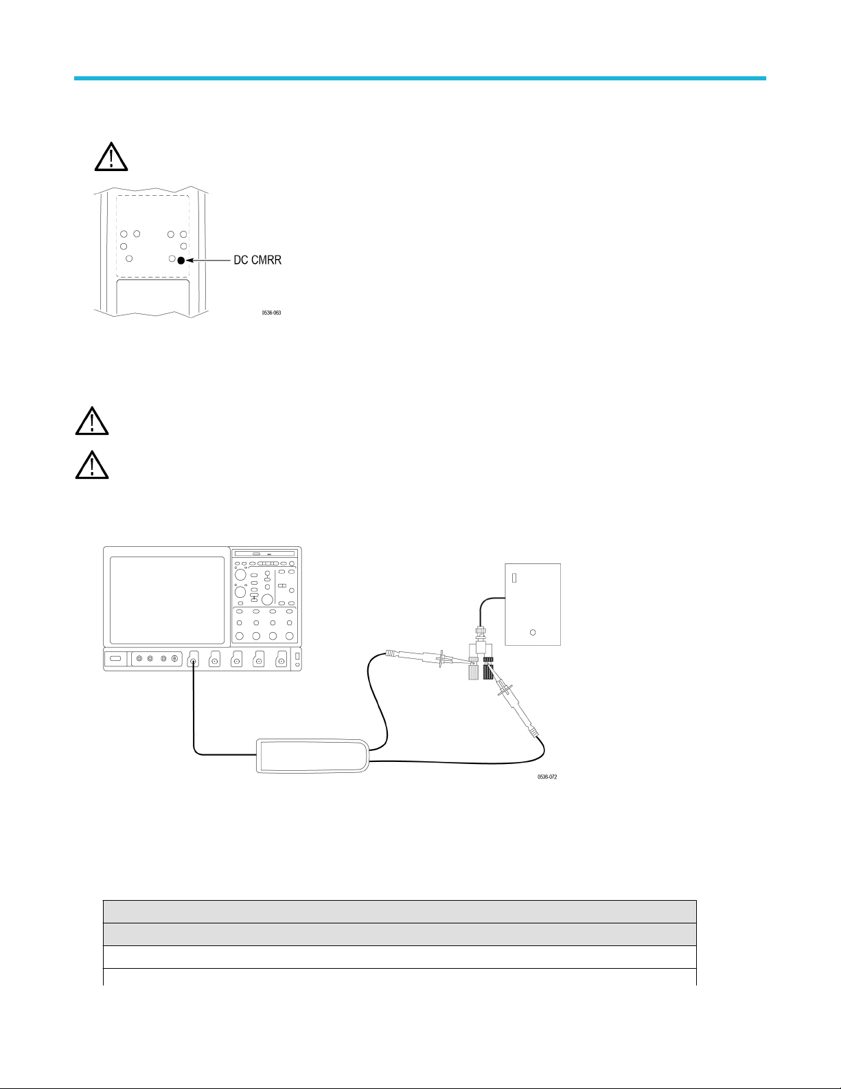
7. Using the narrow-bladed tool, adjust the DC CMRR pot in the probe to minimize the amplitude of the waveform displayed on the
oscilloscope. Use averaging or hi-res filters to make viewing the 40 Hz signal easier
.
WARNING: Use only an insulated tool to make the adjustment. Failure to do so presents a potential shock hazard.
8. Disable the generator output.
LF compensation
WARNING: Dangerous voltages will be present on the calibration generator output terminals and connection cables. Always verify
that the generator is in the standby mode before you make any connections to the generator
.
Note: The TMDP0200 probe only has one long-term +LF adjustment and one long-term –LF adjustment. The other two probe
models have two long-term +LF adjustments and two long-term –LF adjustments each.
1. Verify that the generator output is off.
2. Connect the probe inputs to the signal output connector on the back of the generator, using adapters if necessary. Connect the red
probe lead to the signal, and the black lead to ground.
3. Set the probe attenuation to the lower range for the probe that you are adjusting.
4. Set the oscilloscope horizontal to 4
μs/div, acq mode = average 16.
5. Set the generator fast-rise (rise time waveform) output frequency to 10 kHz.
6. Set the generator fast-rise output voltage to 50 V
p-p
.
Table 17: LF compensation test equipment settings
Probe Generator output
Model Range Voltage (p-p) Frequency
THDP0100 600 V 50 V 10 kHz
Table continued…
Adjustments
58
Probe Generator output
Model Range Voltage (p-p) Frequency
THDP0200 150 V 50 V 10 kHz
TMDP0200 75 V 50 V 10 kHz
7. Enable the generator output. Set the oscilloscope vertical to display the signal.
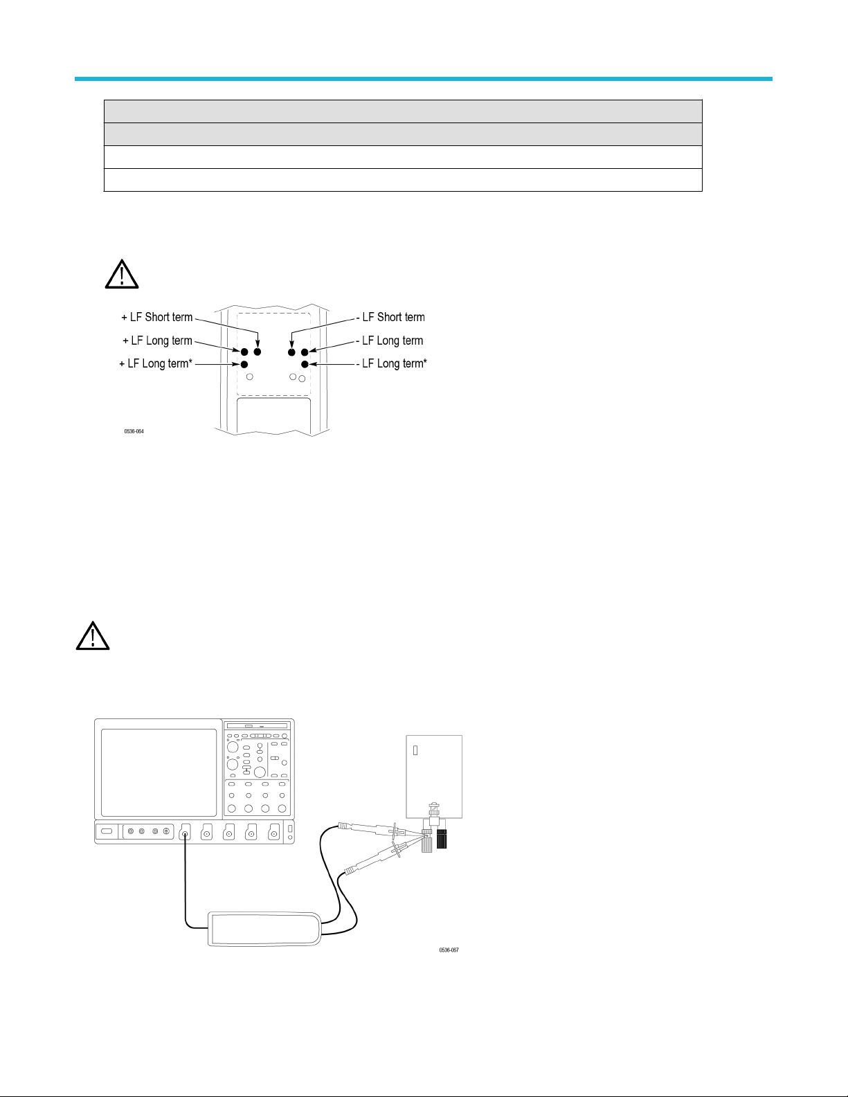
8. Make the adjustments in the following order: long-term +LF
, long-term +LF*, short-term +LF. (The long-term +LF* adjustment is not
used in the TMDP0200 probe.) Repeat this sequence as necessary to optimize the square-wave response.
WARNING: Use only an insulated tool to make the adjustment. Failure to do so presents a potential shock hazard.
9. Disable the generator output.
10. Reverse the probe input leads to the generator
.
11. Invert the signal and trigger slope on the oscilloscope to display the rising edge of the signal. Adjust the trigger level if necessary.
12. Enable the generator output and make the adjustments in the following order: long-term –LF, long-term –LF*, short-term –LF. (The
long-term –LF* adjustment is not used in the TMDP0200 probe.) Repeat this sequence as necessary to optimize the square-wave
response.
AC CMRR
WARNING: Dangerous voltages will be present on the calibration generator output terminals and connection cables. Always verify
that the generator is in the standby mode before you make any connections to the generator
.
1. V
erify that the generator output is off.
2. Connect both of the probe inputs to the red (+) banana connector on the front output of the generator. Use a BNC-banana adapter if
necessary.
3. Set the output of the generator to 297 V
p-p
(105 V
rms) @100 kHz.
Adjustments
High Voltage Differential Probes THDP0100/0200 and TMDP0200 User Manual 59
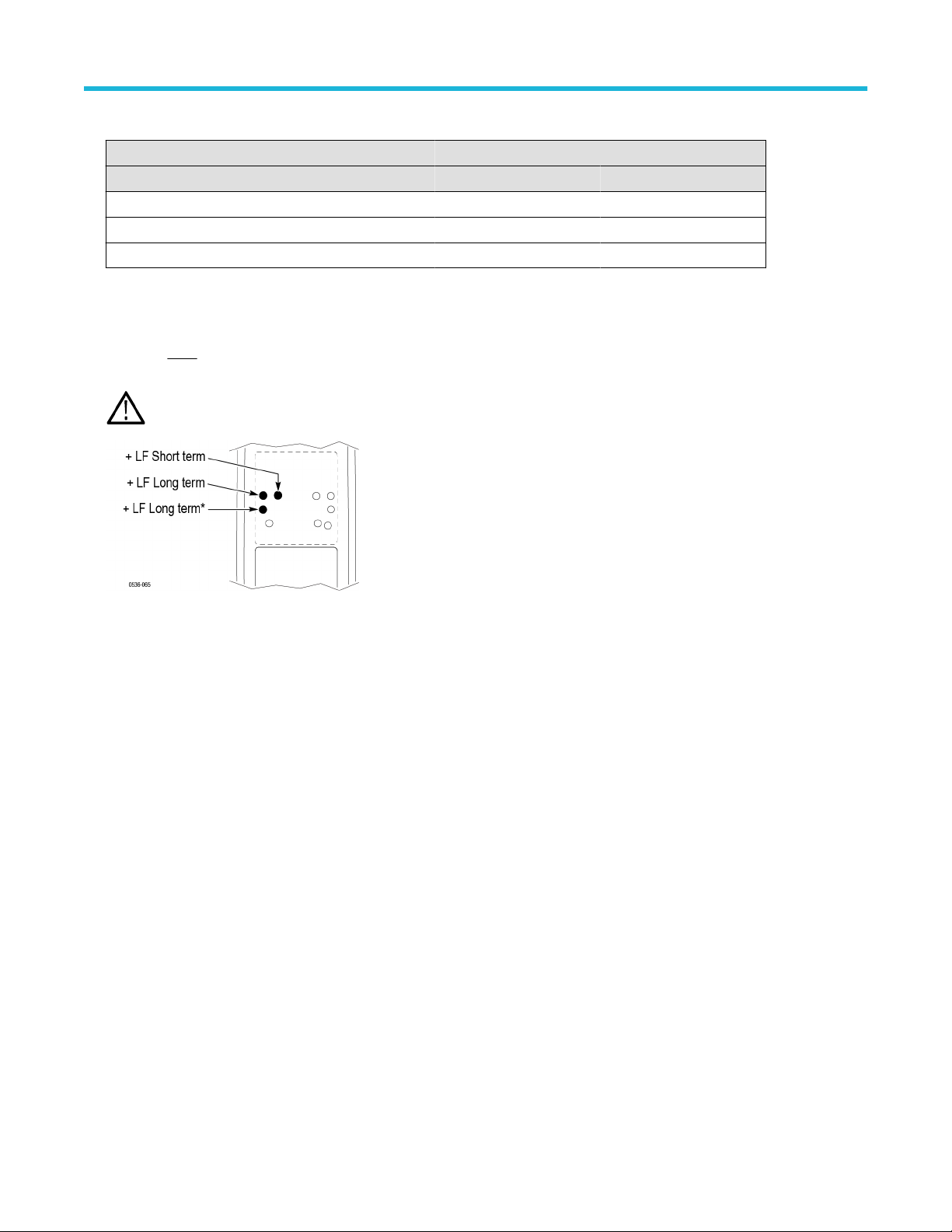
Table 18: AC CMRR test equipment settings
Probe Generator output
Model Range Voltage (p-p) Frequency
THDP0100 600 V 297 V 100 kHz
THDP0200 150 V 297 V 100 kHz
TMDP0200 75 V 297 V 100 kHz
4. Set the oscilloscope horizontal to 10
μs/div.
5. Set the probe bandwidth to full and the attenuation to the lower range of the probe.
6. Enable the generator output. Adjust the oscilloscope vertical to display the signal.
7. Make only
slight adjustments to only the +LF pots to optimize the CMRR (minimize the signal amplitude). Adjust the pots in the
following order: short-term +LF
, long-term +LF, long-term +LF*. (The long-term +LF* adjustment is not used in the TMDP0200 probe.)
WARNING: Use only an insulated tool to make the adjustment. Failure to do so presents a potential shock hazard.
This completes the adjustment procedures.
Adjustments
60