HF Circuit .pdf - 第128页
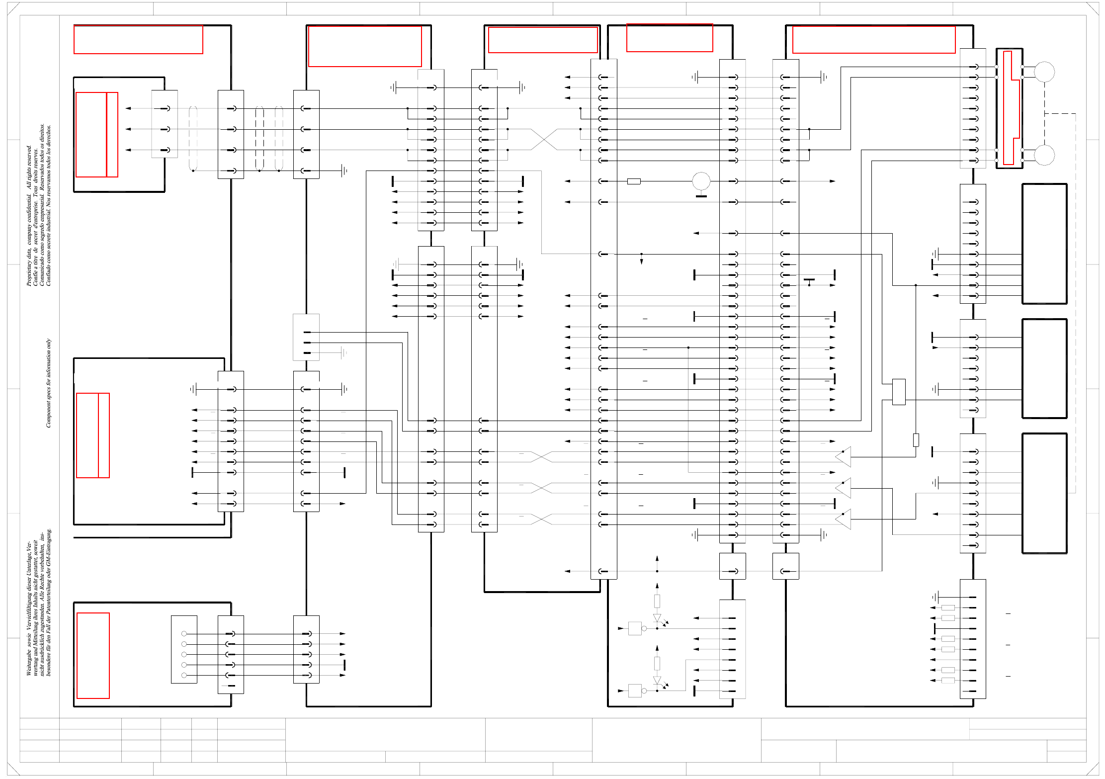
2 - 78 ZCP01_ HF3-0 10201LD 3 Z axis, Collect &Place h ead, gant ry 1, H F/3 (S h. 2 of 3) 20a,c 18c 26c 24a,c 22c 16c 12c 14c 12A 10c X1sy 8c 10A 8A 6A 6c Servo amplifier SDS 60/3 Z1 03002141-xx A11 (sy) 12 6 10 11 …
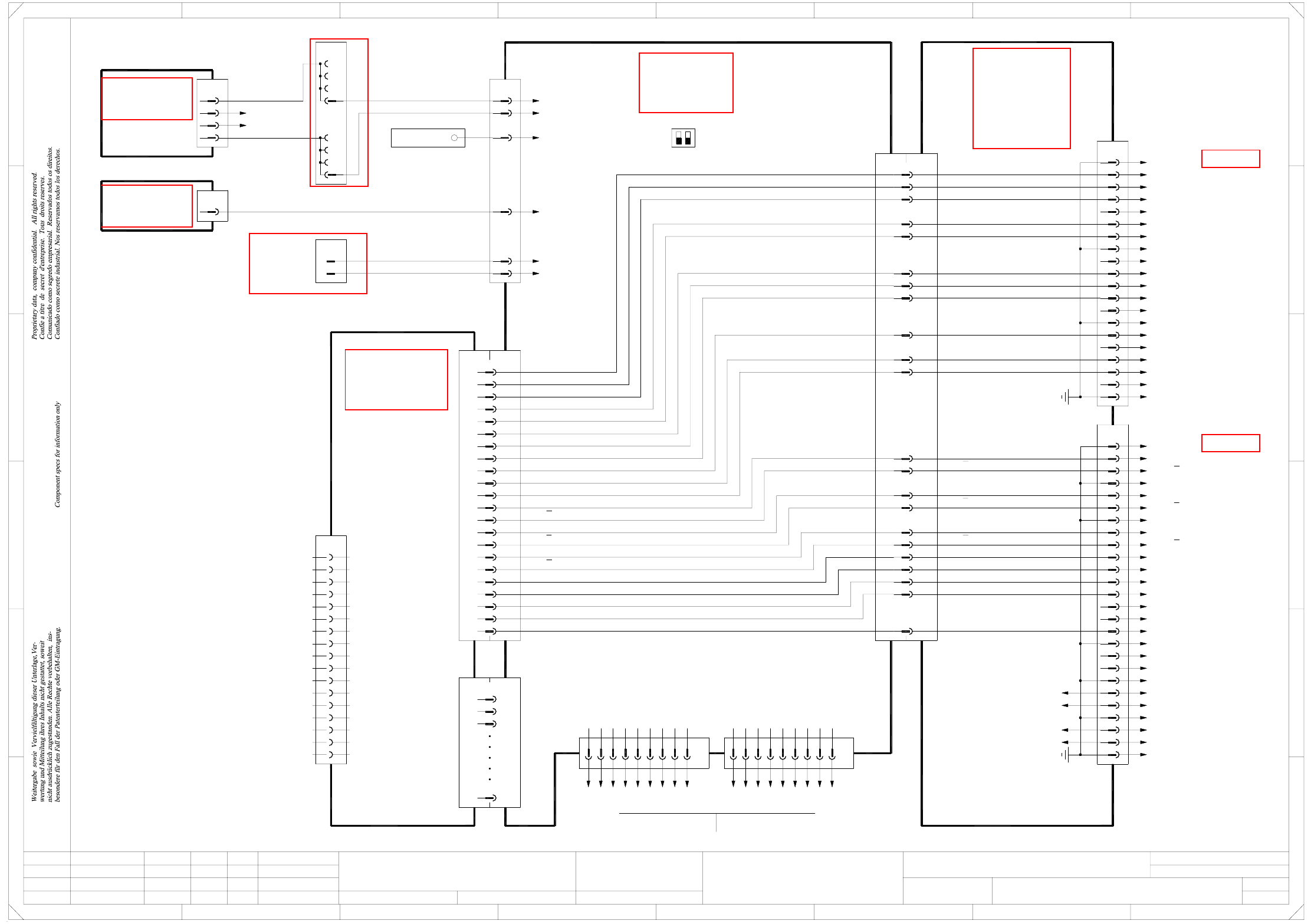
2 - 77
ZCP01_HF3-010201LD3 Z axis, Collect&Place head, gantry 1, HF/3 (Sh. 1 of 3)
10
20
21
23
22
24
25
27
28
26
30
31
33
32
29
GND
4
7
8
9
5
6
2
3
DP track B
29
32
33
31
30
DP track B
DP track A
DP track A
26
28
27
25
24
22
23
21
20
10
DP track N
DP track N
4
7
8
9
5
6
X1as
2
3
Z motor W
Z motor V
36
39
40
38
37
35
34
36
39
40
38
37
35
34
1919
1 1
13
16
17
18
14
15
11
12
13
16
17
18
14
15
11
12
AGND
PE
AGNDPE
n.u.
n.u.
n.u.
n.u.
=
Date
Check.
Stand.
Author
Sheet
Orig. Repl. f. Repl. byNameDateModifiedStatus
Sh.
+
2
F
3
F
8
A
2
D
3
C
B
A
5
B
41
E
5
41
Z axis, Collect&Place head
Function st.
C
D
E
678
76
1.
2.
1.
09.02.04
22.09.05
22.09.05
09.02.2004
Hi
ZCP01_HF3-010201LD3
1
3
Hi
Hi
Hi
Product st.
Document st.
SIPLACE HF series
ZCP01_HF3-010201LD3_SH01.DWG
CAD file :
Mat. no. :
Gantry 1
00330648-xx (as)
SP6-12 intermediate distributor board, digital
03004333-W1
Flat ribbon cable
DLM-X head adapter
03019066-xx (aq)
X14aq
n.u.
+15V
n.u.
GNDGND
GND
9
10
3
6
8
7
5
4
2
1
X10as
Output
Light barrier
"Z axis top"
AGND
GND
+5V
00347297-xx
GND
AGND
7
10
8
9
1
4
5
6
2
3
X13as
VCC
Track N
Track N
AGND
GND
Track B
Track B
Track A
Track A
Test plug
X22ac/J3
81
137
139
101
99
95
97
105
103 Z motor U1
Z motor U2
Z motor W1
Z motor W2
Z motor V1
Z motor V2
LO-RESET
Z motor U
Z motor W
Z motor V
CS_A*
X13ac:48
+15V
Head interface
03000901-xx (ac)
6
7
5
3
4
2
X7ac
1,8,9,10,34 PE
GND
19+5V +5V19
19 19 +5V
Z sensor stop
12 12+5V +5V
Z sensor stop
X141
2
3, 4
1
PE
Z tachom.-
Z tachom.+
n.u.
n.u.
X6as:1
Forced air valve
Reference point
Sensor stop
HI_TRUE
n.u.
GND
n.u.
GND
GND
X2as:22
-15V
Z tachom.-
Z tachom.+
Z track N
Z track N
VCC
Z track B
Z track B
Z track A
Z track A
GND
Z track A
Z track A
Z track B
Z track B
Z track N
Z track N
+15V
31
33
39
35
37
41
88, 90
43
45
Z tachom.-
Z tachom.+
-15V87, 89
-15V
17
15
DP track A
DP track A
DP track B
DP track B
19
21
DP track N
DP track N23
25
VCC83, 85
VCC
DP tachom. +
DP tachom. -
29
27
X8ac:33
X8ac:32
X8ac:30
X8ac:29
X8ac:23
X8ac:26
X8ac:27
X8ac:24
23
24
Z tachom.-
Z tachom.+
23
24
1, 10, 34
Z-axis track signals
X50aa
2
1
3
4
5 +5V
+15V
-15V
+24V
GND
Z1 motor
Cable carrier interface
03009763-xx
Z1 axis
Actual value
03009774-xx
42
43
44
41
X31
wh
gn
bn
bk bk
bn
gn
wh
3
2
X3sy
1
bk
rd
bn
bk
rd
bn
wh
03002163-W3
(Cable)
Gantries 1 or 3 Gantry 1
Z motor U
Z motor V
Z motor W
Servo ampl. backplane
Z axis / Collect&Place head
00353484-xx A39 (sy)
Axis unit
03016110-xx
X1sp
1,4,7,17,20,23,26
PE
2
3
5
6
8
9
10
11
GND
Z track N
Z track N
Z track B
Z track B
Z track A
Z track A
00353487-xx A47 (sp)
Axis distributor I/O
Sheet 3/D7
Cable carrier interface
03009768-W1/W2
(W1)wh
2
1
KEY
gn
bn
(W2)
(W2)
(W1)
(W1)
wh
or
X1ra_+24V
X1ra_+15V
X1ra_+5V
X1ra_0V
X1ra_-15V
pk
rd
bu
X1ra
1
4
6
5
3
2
X5ra
Voltage
Sub-distributor
03010005-xx (ra)
SIPLACE HF
Sheet 2 / E7
22 22 -15V
25 25 +15V
28 28 +24V
VCC
9
8
pulse
+5V
4AGND
6
5
3
2
X4as
1
angular position encoder
Incremental
00321220-xx
n.u.
Zero
bn
wh
gn Track A
ye
Key
Track Bgy
Track N
Track B
Track A
n.u.
6x470 Ω
H5 green
X1as:38
X1as:39
X1as:36
X1as:35
X1as:33
X1as:32
5
8
7
6
2
4
3
1
TP
GND
VCC
LSM
LSZD
LSVA
LSVZ
LZUS
VCC
H6 green
VCC
LZOS
OBEN_SP
E_LIS_Z_E_LIS_Z_
S/Z2 motor
03013616-xx
Carrier cable 6
106
X8ac:3,4
X8ac:5
X8ac:2 DP motor U
GND
+5V
HF/3
A&D EA
s
GND
PE
+24V
+15V
-15V
+5V
60
Z clampingX8ac:15
X13ac:49
100
102,104 DP motor V
DP motor W
Z sensor stopZ sensor stop
2
V1
GD
S
1
"Z axis top"
Light barrier
E_LIS_Z_OBEN_SP
E_LIS_Z_UNTEN_SP
Light barrier
"Z axis bottom"
Sensor stop
X13aq X2as
13
13 LO-RESET
UNTEN_SP
X9aq:19
03004333-W2
Flat ribbon cable
(Light barrier
"Z axis bottom"
RESET)
10
9
8
6
7
5
2
3
4
X3as
1
Key
Key
"Z axis top"
VCC
+15V
+15V
5
8
ENABLE
GND
AGND
7
6
+15V
GND
AGND
X11as
2
4
3
1
Light barrier
00321524-xx
"Z axis bottom"
Output
LOGIC
7
GND
10
28
22
25
16, 31
15
Z motor U
Z motor V
Z motor W
GND
-15V
+15V
+24V
X6ac
PE1, 10, 34
16, 31
33
32
30
29
26
27 Z track N
Z track B
Z track A
Z track N
Z track B
Z track A
Z track A
Z track A
Z track B
Z track B
Z track N
Z track N
X7aa
X6aa
Cable carrier interface
03010612-xx (aa)
Carrier cable 7
03013617-xx
Z1/DP1 motor
6
4
5
3
7
2
1,8,9,10,34
28
25
16, 31
22
15
+24V
+15V
-15V
GND
PE
16, 31
27
26
29
30
32
33
X14aa
1
2
3
4 PE
Z motor U
Z motor V
Z motor W
X24aa
1,4,7,17,20,23,26
2
PE
3
5
6
11
10
8
9
GND
Z track N
Z track N
Z track B
Z track B
Z track A
Z track A
wh
73
wh
4
bu
8
tbu
00321220-xx
Interfere. suppress. board, Z motor
03014578-xx
2
1
bk
rd
6
5
Mbk
rd
See page 5-57
See page 4-18
See page 5-61
See page 5-8
See page 5-22
See page 5-27
See page 5-44
See page 4-8
See page 5-60
2 - 78
ZCP01_HF3-010201LD3 Z axis, Collect&Place head, gantry 1, HF/3 (Sh. 2 of 3)
20a,c
18c
26c
24a,c
22c
16c
12c
14c
12A
10c
X1sy
8c
10A
8A
6A
6c
Servo amplifier
SDS 60/3 Z1
03002141-xx A11 (sy)
12
6
10
11
9
7
8
3
4
5
1
2
X2sy
6
X5sy
5
4
3
1
2
13
16
17
18
14
15
19
20
n.u.
n.u.
n.u.
n.u.
J²t
PE
Servo Enable +
Servo Enable -
Servo Ready
Inom W
AGND
Inom U
Link voltage impressed
ADR2
ADR1
ADR3
ADR4
X3sy
Z motor W
Z motor V
Z motor U
03002163-W3
(Cable)
20
18
19
17
15
16
X2sp
4
5
6
=
Date
Check.
Stand.
Author
Sheet
Orig. Repl. f. Repl. byNameDateModifiedStatus
Sh.
+
2
F
3
F
8
A
2
D
3
C
B
A
5
B
41
E
5
41
C
D
Z axis, Collect&Place head
Function st.
E
678
76
1.
2.
1.
09.02.04
22.09.05
22.09.05
09.02.2004
Hi
ZCP01_HF3-010201LD3
2
3
Hi
Hi
Hi
Product st.
Document st.
SIPLACE HF series
ZCP01_HF3-010201LD3_SH02.DWG
CAD file :
Mat. no. :
18a
28a,c
32a,c
30a,c
7
bk
wh
bk
16
25
23
n.u.
(W1)
(W1)
(W1)
(W1)
(W1)
(W2)
(W2)
gnye
Z/DP+ link voltage
Star+ link voltage
PE
Z/DP- link voltage
Vin_axis+
Vin_axis-
Z/DP+
X4tv:4
4e
4f
3e
4b
4d
4c
4a
3f
X4wo
3b
vi
3d
3c
3A
X3wo:Z28, X2wo:Z28
X3wo:D30, X2wo:Z30
(DC/DC converter)
(DC/DC converter)
12
vi
X4sv:4
HF/3
A&D EA
s
X33
X31
13
bn
Power supply
00354626-xx
X14
1
1
03009766-xx W1+W2
(Cable)
4c
4a
2a
2c
-15V
+15V
GND
ADR1
ADR2
ADR3
ADR4
Link voltage impressed
Servo Ready
AGND
Inom W
Inom U
Servo Enable
J²t
R31
L3
L2
R21
L1
R11
Z motor V
Z motor U
Z motor W
Gantry 1
C1
R12
R22
C2
R32
C3
Z/DP+ link voltage
Star+ link voltage
Star+
42
44
43
X31
41
bn
rd
bk
wh
vi
bu
or
wh
142
3
bn
vi11
PE
1
6
4
2
4
3
9
1
2
3
7
12
11
10
9
8
13
14
PE
Flat ribbon cable
20x0.09mm²
X5wo
3d
3e
3c
3b
3A
4a
4d
4b
4c
3f
4e
4f
A39 (sy)
00353484-xx
Z axis / Collect&Place head
Servo backplane
n.u.
n.u.
Link voltage impressed
AGND
Inom W
Inom U
n.u.
Servo Ready
n.u.
Servo Enable -
Servo Enable +
A47 (sp)
Axis distributor I/O
00353487-xx
1
2
3
00353449-xx
5V/15V
DC/DC converter
A17
X2wo
d6
d10
or +15V (Servo)
bu -15V (Servo)
Sheet 3 / B7
Sheet 1 / A2
n.u.
n.u.
n.u.
n.u.
n.u.
n.u.
n.u.
n.u.
X4sy
Z/DP+5
4
3
1
2
n.u.
n.u.
n.u.
n.u.
-15V
+15V
GND
bu
or
wh
n.u.
See page 5-19
See page 3-7
See page 5-27
See page 5-22
See page 5-25
See page 5-25
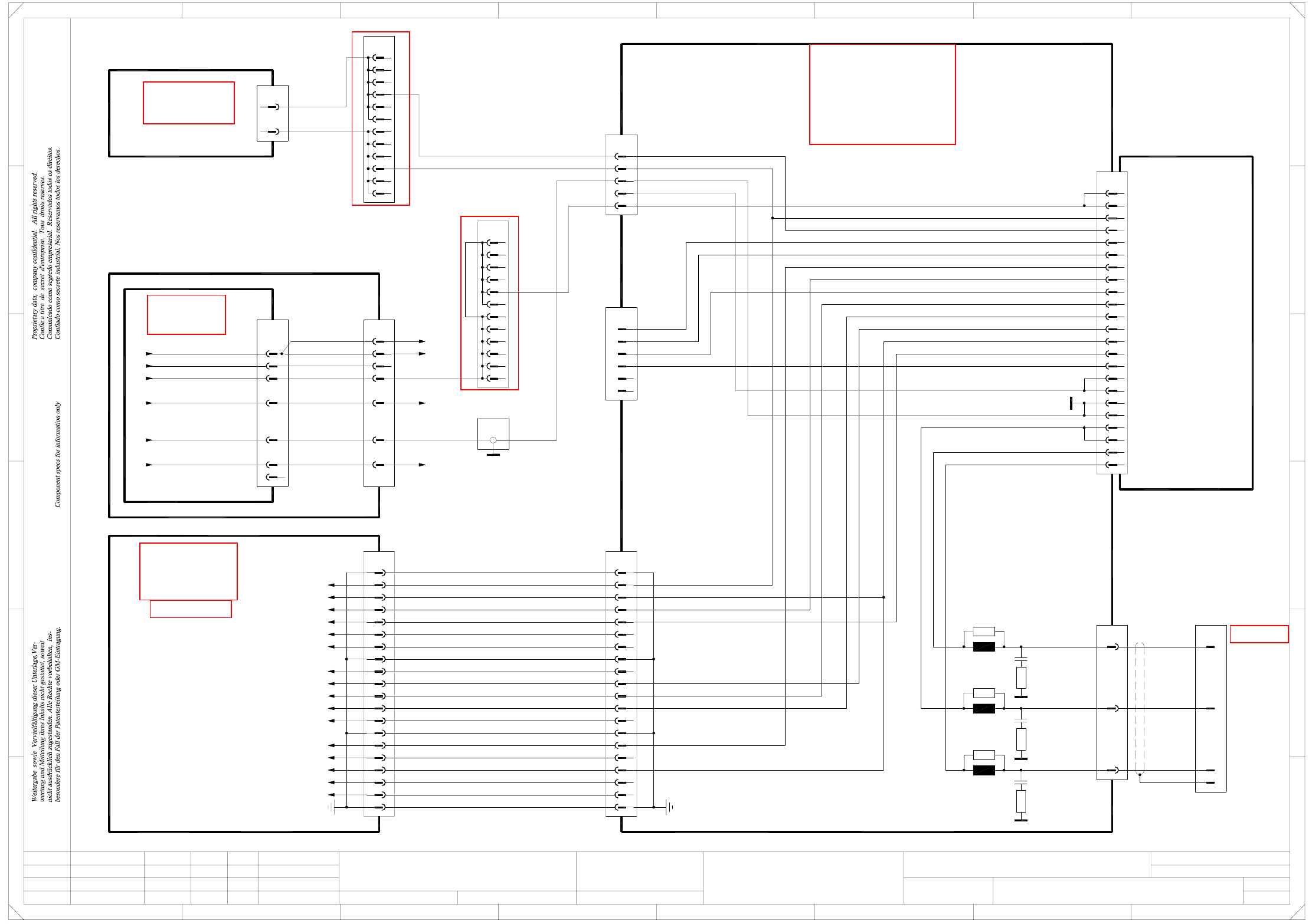
2 - 79
ZCP01_HF3-010201LD3 Z axis, Collect&Place head, gantry 1, HF/3 (Sh. 3 of 3)
Inom W
AGND
Inom U
Link voltage impressed
20
18
19
17
15
16
X2sp
4
5
6
1
2
3
7
12
11
10
9
8
13
14
PE
n.u.
n.u.
n.u.
n.u.
n.u.
Flat ribbon cable
20x0.09mm²
n.u.
n.u.
Link voltage impressed
AGND
Inom W
Inom U
n.u.
Servo Ready
n.u.
Servo Enable -
Servo Enable +
A47 (sp)
Axis distributor I/O
00353487-xx
PE
1
20
19
17
18
16
14
15
13
7
10
11
12
8
9
4
6
5
3
2
X1sp
25
23
24
22
21
26
C10
C8
A2
A1
A8
A9
B3
A3
C7
C5
B5
B9
C9
X7sp
=
Date
Check.
Stand.
Author
Sheet
Orig. Repl. f. Repl. byNameDateModifiedStatus
Sh.
+
2
F
3
F
8
A
2
D
3
C
B
A
5
B
41
E
5
41
C
D
Z axis, Collect&Place head
Function st.
E
678
76
1.
2.
1.
09.02.04
22.09.05
22.09.05
09.02.2004
Hi
ZCP01_HF3-010201LD3
3
3
Hi
Hi
Hi
Product st.
Document st.
SIPLACE HF series
ZCP01_HF3-010201LD3_SH03.DWG
CAD file :
Mat. no. :
Servo Enable +
Servo Enable -
Servo Ready
B1
A2
A1
Z track A
Z track N
Z track B
Z track N
Z track B
Z track A
A8
C8
A9
B3
C10
A3
C7
C5
B5
B9
C9
Link voltage impressed
Inom W
AGND
Inom U
Servo Ready
Servo Enable -
Servo Enable +
PE
PE
PE
PE
PE
PE
PE
PE
PE
PE
GND
03009774-xx
Act. value, Z1 axis
Gantry 1
GNDA28
GNDA28
Gantry 1
C&P head
C4
C4
Z sensor stop
Z sensor stop
+5V
+5V
HF/3
12
Axis unit Axis unit
A&D EA
s
4
03010051-xx
Power failure
8
RESET
9
n.u.
GND
CAN_H
CAN_INT
6
7
5
X30_2tq
X30_1tq
03010051-xx
Flat ribbon cable
Sheet 1 / D2
Sheet 2 / E3
6
X10tq
3
5
4
2
1
-15V
+15V
GND
VCC
Power failure
Power failure
rd
bk
bk
dkbu
wh
pk
X33
Ground bus bar
DC/DC converter
00353450-xx
±15V
A18
2d
dkbu
dkbu
d22
X3wo
z20
2b
2c
pk
2a
X5wo
1d
1c
1A
1b
dkbu
Z4
d6
pk
pk
+15V axis
-15V axis
-15V / X21:19
+15V / X21:17
5V/15V
00353449-xx A17
DC/DC converter
X2wo
z16 rd VCC
X31
21 bk
12 bk
Power failure
Power failure
S1
ON
OFF
B4
A5
A4
C2
C1
B2
CAN_H
CAN bus
CAN_L
GND
1-Wire
2
3
1
RESET
n.u.
9
8
Power failure
GND
CAN_INT
GND
7
6
5
4
CAN bus
1-Wire
CAN_L
3
2
1
B2
B1
C2
C1
A5
A4
B4
Z track A
Z track A
Z track B
Z track B
Z track N
Z track N
Z sensor stop
PE
+5V
n.u.
n.u.
n.u.
n.u.
n.u.
n.u.
n.u.
n.u.
n.u.
n.u.
Z track B
Z track N
Z track N
Z track B
Z track A
Z track A
X6tq
X6tqX2sb
X1sb
A/B/C1
X2tq
A/B/C32
A/B/C2
A/B/C3
SMP bus
A44 (tq)
Backplane, axis
00353485-xx
Z-axis axis board
A22 (sb)
00350575-xx
3
35
36
37
9
12
20
34
11
10
6
8
7
5
4
X3sb
2
1
VCC
-15V
+15V
TRIG
CAN_L
CAN_H
VREG
GND
INDEX
End signal
COUNT B
COUNT A
Inom
Vnom
RxD
TxD
AGND
See page 5-20
See page 5-19
See page 5-25
See page 5-27
See page 5-23
See page 5-13
See page 4-20