HF Circuit .pdf - 第55页
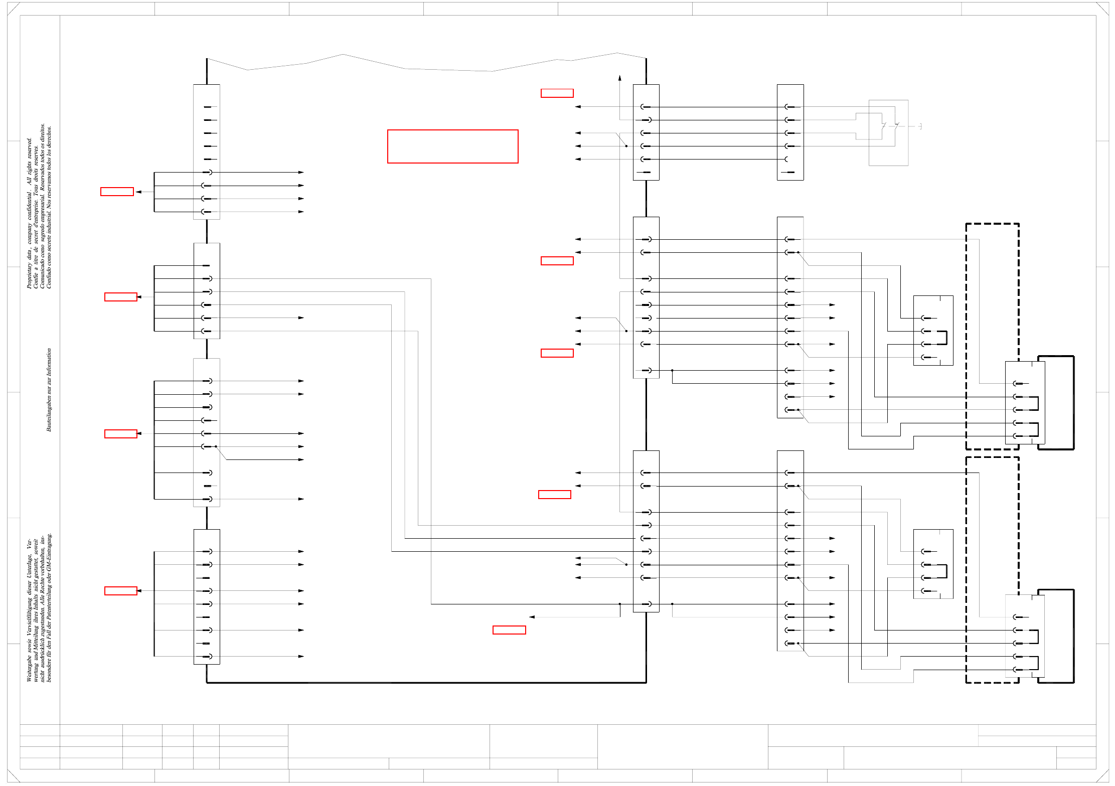
2 - 5 NH-050 101LD3 Emerg. -stop lo op, EME RG .-S TOP butto n, ST ART/ STOP button, protect ive swit ches (Sh. 5 of 5 ) = + 2 F 3 F 8 A 2 D 3 C B A 5 B 4 1 E 5 4 1 1 3 2 X8rb A1 3 6 n.u. n.u. 7 8 4 5 X7rb 1 2 X1ra_StopB…
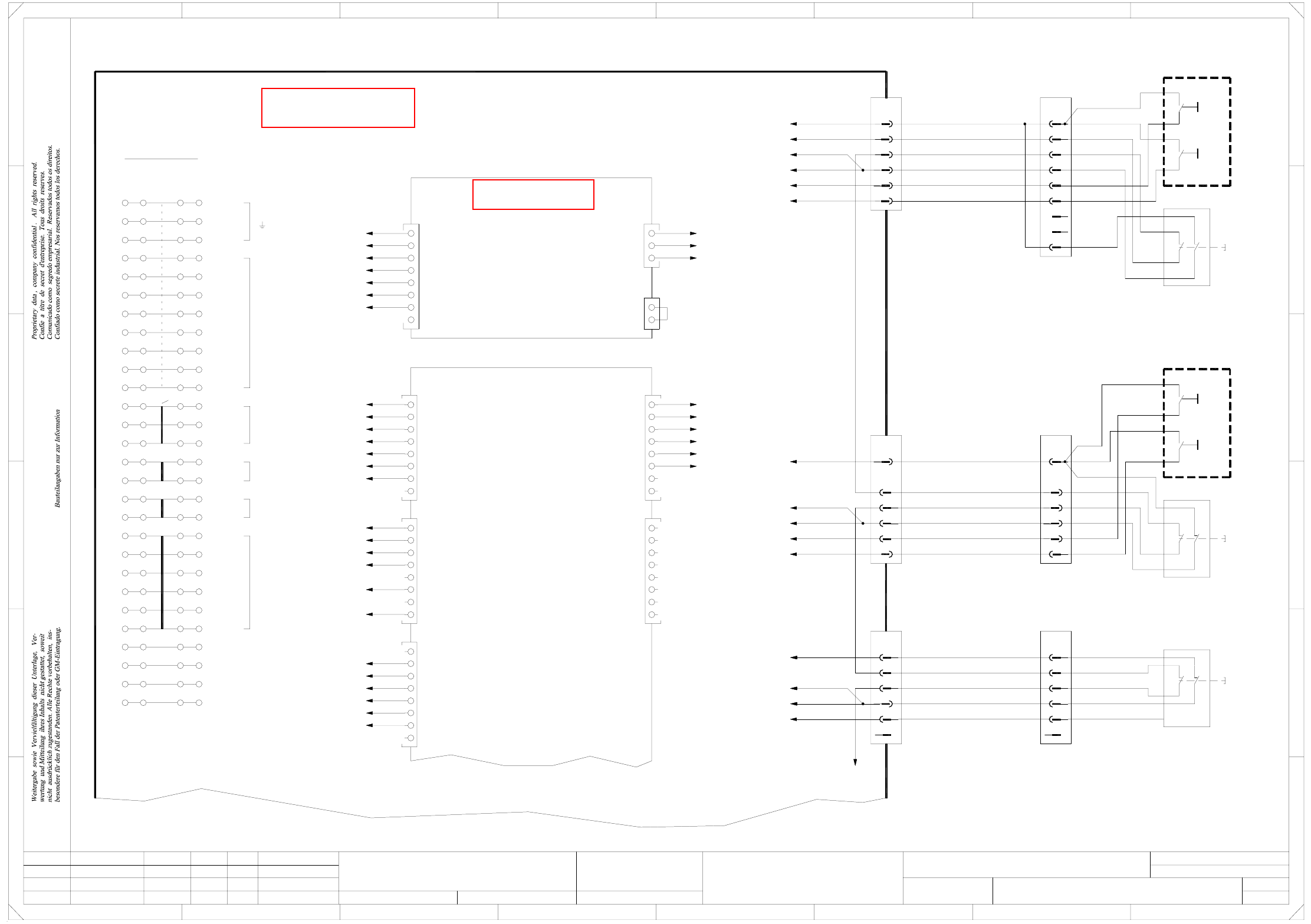
2 - 4
NH-050101LD3 Emerg.-stop loop, EMERG.-STOP button,
START/STOP button, protective switches (Sh. 4 of 5)
10
9
(W1)
(W1)
Location 4
Component trolley
E29/30
D29/30 rd
bkB29/30
C29/30
X140
5(W1)
ye
8
(W2)
(W1)
6
7
(W1)
(W1)
bn
4(W1)
(W2)
wh
2
(W2)
(W1)
X14f
4
3
2
1
bk
03021042
Adapter connector
CO flap
1(W1)
03021020-W1/W2
(Cable)
Location 4
Component trolley, docking unit
wh
gy
X1ra_Vin(+) illumination
Sub-distributor
03010005 (ra)
Emergency-stopLoopMTC4 in
Emergency-stopLoopMTC4 out
S_Emergency-stopButtonMTC
wh
bk
bk
X1ra_Flap
S_Emergency-stopButtonMTC
X4rb_8(DI15)
CAN I/O module
S_Flap
X1ra_Flap
n.u.
n.u.
GND
X1ra_0V
wh
9
9
8
bk
n.u.
Emergency-stopLoopMTC4 out
S_Flap
S_StartButton
S_StopButton
3
5
7
6
4
bk
bk
2
1
X73ra
bk
bk
Emergency-stopLoopMTC4 in
Emergency-stopLoop1output
S_Emerg.StopButtonMTC
=
+
2
F
3
F
8
A
2
D
3
C
B
A
5
B
41
E
5
41
X1re_7 (8x&)
X5rb_7 (DI22)
A29/30
A29/30
n.u.
n.u.
n.u.
Emergency-stopLoop2output
X2re_3 (8x&)
bk
X4ra_6
X24ra_7
(Cable)
03002506-W5
power supply
To plug X18
(sheet 1)
2
1
pk +5V
X1ra_5V
GNDwh
X1ra_0V
+24Vor
wh GND
X1ra_0V
X1ra_24V
bk
bk
bk
n.u.
n.u.
n.u.
n.u.
n.u.
4
1
3
2
(W6)
(W6)
(W6)
(W6)
(W5)
(W5)
X1ra_28
X1ra_28
11
10
X143
7
9
8
6
5
4
3
1
2
X54
6
5
4
3
1
2
n.u.
X14ra
3
5
6
4
2
1
n.u.
9
X18ra
4
8
7
6
5
2
3
1
9
4
8
7
6
5
2
3
X23ra
1
bl
gr&pk
gn&ye
wh&bn
gn&ye
gr&pk
rd
bl
wh&bn
Emergency-stopLoop 1 out
Emergency-stopLoop 1 in
S_Hood4
GND
(Cable)
+24V
03002540-xx
(Cable)
GND
03002542-xx
03002547-xx
GND
(Cable)
+24V
+24V
Emergency-stopLoop 1 in
Emergency-stopLoop 1 out
Emergency-stopLoop 1 out
Emergency-stopLoop 1 in
gnye&1
gnye&1
2&3
4
5
6
7
8
9
10
11
n.u.
n.u.
2&3
4
5
6
7
8
9
10
11
n.u.
n.u.
S_Flap
S_Flap
S_COtable1
S_COtable4
X13ra_3
To plug
or
X1ra_24V
+24V
bk
X1ra_0V
GND
bk
bk
bk
2
6
5
3
4
bk
bk
bk
1
X72ra
1
Voltage illuminationA
Voltage illuminationB
Voltage tape cutter
n.u.
7
8
6
gy
gy
bk
3
5
4
2
X71ra
gn&ye (W3)
2(W3)
3(W3)
1(W3)
(W2)
(W2)
(W2)
(W1)
(W1)
(W1)
bn
gn
bn
wh
gn
wh
rd
gn
ye
gy
pk
gn
bn
wh
main distributor
To plug X73qa
03003221-xx
(sheet 3)
(Cable)
Emergency-stopLoop1OK
X1ra_StartButton
X1ra_Flap
X1ra_StopButton
X3rb_1(DI0)
CAN I/O module
(Cable)
(sheet 3)
03002520-W1/W2
To plug X72qa
main distributor
X2rc_7
X2rc_9
X17ra_4
(VillB)
(VillA)
(Cable)
main distributor
(sheet 3)
To plug X71qa
03002519-W1/W2/W3
(sheet 5)
(sheet 5)
(sheet 5)
(sheet 5)
(sheet 5)
(sheet 5)
(sheet 5)
(sheet 5)
5. 22.09.05
s
A&D EA
NH-050101LD3
X24ra_4
X1re_6 (8x&)
X1re_3 (8x&)
X5rb_3 (DI18)
wh
bk
wh
or
X1ra_0V
GND
X1ra_24V
+24V
bk
bk
X1ra_24V
X1ra_0V
+24V
GND
or
wh
bk
n.u.
n.u.
n.u.
bk
S_Flap bk
bk
n.u.
X1ra_0V
Hood switch
Location 4
1121
1222
03020409-xx
(Cable)
(W2)wh
(W1)
(W1)1
2
(W1)
(W2)bn
4
5(W1)
(W1)6
(W1)
(W1)7
8
(W2)ye
(W1)
(W1)9
10
(W1)11
(W1)
(W2)gn
3
X11f
1
2
3
4
bk
Component trolley, docking unit
Location 1
Adapter connector
CO flap
03021042
X110
E29/30
B29/30
C29/30
D29/30
bk
rd
Location 1
Component trolley
(Cable)
03021020-W1/W2
11 (W1)
gn
3(W1)
(W2)
C
D
E
678
76
1.
1.
22.09.05
22.09.05
17.12.2002
Hi
Emergency-stop loop
4
5
Hi
Hi
Hi
Function status
Product status
Doc. status
SIPLACE HF series
Sheet
Sh.
NH-050101LD3_SH04.DWG
Orig. Repl. f. Replaced by
Date
Author
Check.
Stand.NameDateModifiedStatus
Protective switch
Component trolley, docking unit
CAD file:
Mat. no.:
X113
12
11
10
9
8
7
2
4
6
5
3
1
X3ra
9
8
7
2
4
6
5
3
1
12
See page 4-8
2 - 5
NH-050101LD3 Emerg.-stop loop, EMERG.-STOP button,
START/STOP button, protective switches (Sh. 5 of 5)
=
+
2
F
3
F
8
A
2
D
3
C
B
A
5
B
41
E
5
41
1
3
2
X8rb
A1
3
6
n.u.
n.u.
7
8
4
5
X7rb
1
2
X1ra_StopButton
X1ra_StartButton
bk
bk
bk
5. 22.09.05
s
A&D EA
NH-050101LD3
X5rb_4 (DI19)
X1re_4 (8x&)
bk
bk
X1re_5 (8x&)
X5rb_5 (DI20)
bk
X19ra_4
X1re_2 (8x&)
DI0
DI1
DI2
DI3
DI4
DI5
DI7
DI6
DO7
DO6
DO5
DO4
DO3
DO2
DO1
DO0
DO15
DO14
DO13
DO12
DO11
DO10
DO9
DO8
DI15
DI14
DI13
DI11
DI12
DI10
DI8
DI9
3
6
D23
D22
8
7
D20
D21
D19
5
4
D17
D18
D16
2
1
X5rb
n.u.
n.u.
S_Emerg.StopButtonPCBinput
S_HoodPCBinput
S_COtable4
S_Hood4
S_COtable1
S_Hood1
X11ra_4
(W1)
wh
X61
bn
rd
or
bn
(W2)
(W2)
(W2)
(W1)
(Cable)
S1
3
4
4
Stop
S2
Start
3
bk
wh
or
bk
bk
or
bk
bk
bk
bk
X1ra_24V
or
X23ra_7
X24ra_4
X12ra_4
X19ra_4
X18ra_7
bk
bk
bk
bk
bk
bk
bk
X4ra_4
or
bk
bk
X1ra_24V
bk
X23ra_9
bk
X4ra_6
bk
bk
bk
X20ra_2
X30ra_4
bk
bk
bk
X30ra_3
X73ra_9
X30ra_2
bk
bk
bk
bk
bk
bk
X30ra_7
K1_A1
X30ra_9
X30ra_8
X30ra_6
X30ra_10
X18ra_7
X14ra_4
X23ra_7
X11ra_4
X12ra_4
X13ra_4
X1ra_24V
3
S_COtable13
S_Emerg.StopButtonPCBinput
S_COtable4
S_HoodPCBinput
S_Hood46
n.u.8
7
5
4
X3re
1
2
PCB, 8-input AND gate
A5 (8x&)
Emergency-stopLoop2 (start)
S_Hood12
1
X1re
X1ra_24V
X1ra_0V
2
1
X2re
Emergency-stopLoop2(output)
X72ra_5
X30ra_5
PCB input side, on the left
(W1)
gn
n.u.
n.u.
bk
ye
(W2)
(W1)
Cover flap, PCB conveyor
PCB input side, on the left
1222
1121
03020410-xx
X1ra_PE
-15V
+15V
5V
GND
GROUND
Ctrl_D1ServoSlot
Ctrl_D0ServoSlot
Ctrl_D3ServoSlot
Ctrl_D4ServoSlot
Ctrl_D2ServoSlot
Ctrl_CompressedAirMainValve
n.u.
n.u.
n.u.
n.u.
S_StopButton
S_ControlON
n.u.
S_EmergencyStopButtonMTC
n.u.
S_RejectBin
S_StartButton
S_GantryCrash2
4
7
8
5
6
1
3
2
X4rb
EmergencyStopLoopOK
S_PressureSensorMainValve
S_D1ServoAddressBus
S_D2ServoAddressBus
S_D3ServoAddressBus
S_D0ServoAddressBus
CAN I/O module
3
5
4
6
8
7
M_vacuum pumpON
n.u.
2
1
X3rb
4
n.u.
7
n.u.
8
n.u.
n.u.
6
5
Bridge
X1ra_5V
X1ra_5V
X1ra_0V
X1ra_0V
X1ra_0V
X1ra_0V
X1ra_0V
Terminals overview
X1ra
2
4
3
5
1
ab
X1ra_PE
X1ra_0V
X1ra_0V
X1ra_PE
cd
C
D
E
678
76
1.
1.
22.09.05
22.09.05
17.12.2002
Hi
Emergency-stop loop
5
5
Hi
Hi
Hi
Function status
Product status
Doc. status
SIPLACE HF series
Sheet
Sh.
NH-050101LD3_SH05.DWG
Orig. Repl. f. Replaced by
Date
Author
Check.
Stand.NameDateModifiedStatus
START buttons, STOP buttons
Protective switch
Emergency-stop push-button
CAD file:
Mat. no.:
03002538-xx
Emergency-stopLoop 1 out
Emergency-stopLoop 1 in
S_Emerg.StopButtonPCBinput
+24V
(Cable)
3
5
6
4
2
1
bk
bk
or+24V
bk
bk
bl
pk
bn&gn
wh
ye&gy
X12ra
bk
rd
pk&bu
ye&gy
bn
wh
6
5
4
1
3
2
X64
12
11
22
21
(Cable)
03002537-xx
+24V
Emergency-stopLoop 1 in
Emergency-stopLoop 1 out
S_HoodPCBinput
6
4
5
3
2
1
bk
+24V
or
X11ra
2
6
5
4
3
1
gn
vi
EMERGENCY STOP
S3
4
3
4
3
Stop
S2
Start
S1
bk
X14ra_2
To plug
X1ra_24V
S_StartButton
S_StopButtonrd
X1ra_StartButton
X1ra_StopButton
rd
bl
ye&gy
bn&gn
pk
wh
S_StopButton
S_StartButton
X1ra_StartButton
X1ra_StopButton
7
8
9
X1ra_24V
03010005 (ra)
Sub-distributor
S_Hood1
Emergency-stopLoop 1 out
Emergency-stopLoop 1 in
+24V
GND
03002539-xx
(Cable)
gr&pk
rd
bl
wh&bn
gn&ye
wh&bn
bl
rd
gr&pk
gn&ye
n.u.
6
5
4
1
2
3
X51
22
(Cable)
03020409-xx
21
12
Hood 1
11
1
2
3
5
4
6
X13ra
bk
n.u.
wh
bk
or
bk
X1ra_0V
GND
X1ra_24V
+24V
PCB input side on the right Hood switch
S_StartButton
S_StopButton
03020687-xx
(Cable)
X1ra_24V
or
+24V
S_StartButton
S_StopButton
Emergency-stop loop start
X1ra_24V21
24V
X1ra_Flap
X1ra_Vin(+)ill
X1ra_StartButton
X1ra_StopButton
X1ra_24V
X1ra_24V
X1ra_24V
25
27
28
26
23
24
22
(DC/DC converter)
X1ra_24V
X1ra_24V
X1ra_-15V
X1ra_-15V
X1ra_+15V
X1ra_+15V
X1ra_0V6
20
19
18
17
16
15
14 X1ra_5V
13
12
11
10
7
8
9
See page 4-8
See page 5-52
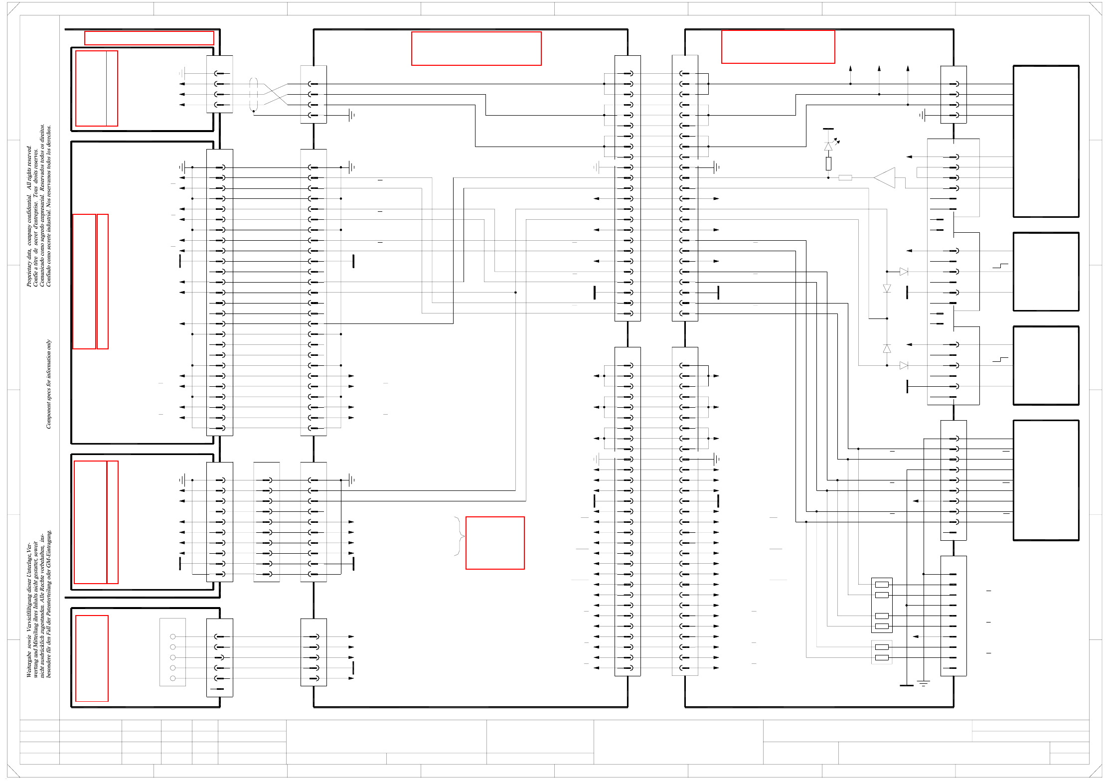
2 - 6
X01-010201LD3 X axis, gantry 1, HF (Sh. 1 of 3)
2
12
15
17
16, 31
13
1, 11, 14, 34
10
27
30
32
33
28
29
20
24
26
25
23
22
19
18
7
33
31
32
30
28
29
27
21
24
25
26
22
23
10
20
1, 11-19, 34
9
8
X4bc
4
6
5
3
2
3
2
X12bc
1
4
3
4
2
X11bc
1
6
5
1
4
6
5
3
2
X16bc
5
6
X17bc
2
3
4
1
5
6
4
3
X15bc
1
2
10
9
8
7
X24bc
6
9
10
8
7
3
5
4
2
1
PE
=
Date
Check.
Stand.
Author
Sheet
Orig. Repl. f. Repl. byNameDateModifiedStatus
Sh.
+
2
F
3
F
8
A
2
D
3
C
B
A
5
B
41
E
5
41
C
D
E
X axis, gantry 1
Function st.
678
76
1.
2.
1.
09.02.04
22.09.05
22.09.05
09.02.2004
Hi
X01_HF-010201LD3
1
3
Hi
Hi
Hi
Product st.
Document st.
SIPLACE HF series
X01_HF-010201LD3_SH01.DWG
CAD file :
Mat. no. :
7
8
9
6
5
X5bc
4
3
5
29
33
32
30
23
26
28
27
25
24
20
22
21
19
18
1, 11, 14, 34
16, 31
17
15
12
13
9
10
8
6
7
2
3
4
29
32
33
31
30
23
26
28
27
25
24
1, 11-19, 34
22
21
20
10
8
9
7
5
6
4
2
3
Carrier cable 4
03001724-xx
X motor
X motor
03001725-xx
Carrier cable 5
PE
-15V
+15V
+24V
GND
X temperature sensor
X limit switch
X reference point
X track B
X track A
X track A
X track B
X track N
X track N
X-B2
X motor U
X motor W
X motor V
Cable carrier interface, gantry 1 or 3
03010612-xx (ba)
S/Z2 sensor stop
S/Z2 force sensor CLK
S/Z2 force sensor CLK
S/Z2 force sensor CS
S/Z2 force sensor DATA
S/Z2 force sensor DATA
S/Z2 force sensor CS
S/Z2 track A
S/Z2 track A
S/Z2 track B
S/Z2 track B
S/Z2 track N
+24V
S/Z2 track N
+15V
-15V
+5V
Spare
GND
PE
Z2-Dir
X12ba:3
X motor W
X12ba:2
X motor V
X12ba:1
X motor U
X12ba
1
2
3
4
X motor V
X motor W
X motor U
X6qa
2
5
4
3
1
9
8
10
6
7
6
4
5
3
2
1
X1qa
X1qa_+24V
X1qa_-15V
X1qa_+15V
X1qa_0V
X1qa_+5V
03010004-xx (qa)
Main distributor
bn
2
KEY
1
gn
wh
(W2)
(W2)
(W1)
(W1)
(W1)
03009788-W1/W2
Cable carrier interface, voltage
Crash signal
03009797-xx
26
25
23
24
22
20
21
19
17
18
13
16
14
15
7
10
12
11
9
8
5
6
2
4
3
1
Actual value
X axis
03009791-xx
n.u.
wh
gn
bn
gn
bn
wh
X motor
03009780-xx
n.u.
Y reference point
Y distance
GND
Y-B2
Y sensor stop
X-B2
X reference point
n.u.
n.u.
n.u.
n.u.
n.u.
R3
470Ω
470Ω
R4
+5V
+5V
X limit switch
-15V
X reference point
X-B2
+15V
X track N
X track N
+24V
X track B
X track B
X track A
X track A
GND
21
S/Z2 track A
S/Z2 track A
+5V
-15V
+15V
+24V
S/Z2 track B
S/Z2 track B
S/Z2 track N
S/Z2 track N
S/Z2 force sensor DATA
S/Z2 force sensor DATA
S/Z2 force sensor CLK
S/Z2 force sensor CLK
S/Z2 force sensor CS
S/Z2 force sensor CS
S/Z2 sensor stop
GND
PE
PE
Spare
Z2-Dir
X motor U
X motor V
X motor W
X12bc:1
X12bc:2
X12bc:3
X4ba
X5ba
X track N
X track N
X track B
X track B
X track A
X track A
GND
X temperature sensor
X reference point
X limit switch
XM track B, n.u.
XM track B, n.u.
XM track A, n.u.
XM track A, n.u.
X motor W
X motor U
X motor V
X5bc:8-10X5bc:5-7X5bc:2-4
bk
See
Drawing
Sheet 1
Y01_HF-xxxxxxLD3
10
9
7
8
6
4
5
3
X35yo_2
1
2
PE PE
PE PE
PE
PE
Axis unit 03016110-xx
00353486-xx A43 (wo)
Backplane anti-crash /
Ballast circuit
Sheet 2 / B3
Sheet 2/D7
00353487-xx A48 (to)
Axis distributor I/O
Sheet 2/F7
00353483-xx A31 (tr)
X axis
Servo ampl. backplane
wh
pk
rd
bu
or
03003361-xx
HF
X10bc
14
13
12
11
10
9
22
21
20
19
18
17
6
5
4
3
2
1
7
Key
8
Key
16
15
Key
Key
03012921-xx
A&D EA
s
X motor U
X motor V
X motor W
1
2
3
PE
03000901-xx (bc)
Head interface, gantry 1
wh
ye
gn
bn
(Cable)
03003361-W1
03003361-W2
(Cable)
Linear motor
X axis
+15V
H7 red
12
+
LM358
X temperature sensor
+24V
GND
+24V
sensor
Reference point
B1
03004108-xx
sensor
03004109-xx
B2
End position
bn
bn
bu
bk
bu
bk
Key
Key
Key
Key
Key
gnwh
gn
wh
ye
pk
rd
bk
bn
gy
Scanning head
X axis
03006472-xx
Screen
T1
T1
GND
T2
T2
+5V
RI
RI
PE
+5V
GND
Track A
Track A
Track B
Track B
Track N
Track N
Test connector, X-axis track signals
GND PE
Track A
Track A
Track B
Track B
Track N
Track N
V2
V4
V5
V3
GND
3
4
2
X22ba
1
8
6
7
5
14
16
15
13
12
10
11
9
22
25
26
24
23
19
21
20
18
17
GND
XM track B, X3ba:29, n.u.
XM track B, X3ba:30, n.u.
XM track A, X3ba:27, n.u.
XM track A, X3ba:26, n.u.
n.u.
n.u.
n.u.
n.u.
n.u.
3
4
2
X31ba
1
8
6
7
5
10
9
X50ba
5
2
4
3
1
X reference point
X-B2
X temperature sensor
X reference point
X limit switch
X track N
X track N
X track B
X track B
X track A
X track A
n.u.
GND
Y sensor stop, X21ba:11
Y reference point, X1ba:29, X21ba:13
Y-B2, X1ba:30
Y distance, X2ba:30
GND
-15V
+24V
+15V
+5V
3
4
2
X4tr
1
X1to
X35wo
See page 5-57
See page 4-18
See page 5-44
See page 5-27
See page 5-25
See page 4-7
See page 2-9