HF Circuit .pdf - 第145页
2 - 95 DPCP04 _HF3-0 10201 LD3 DP axis , Colle ct&Place head, gan try 4, H F/3 (S h. 1 of 3) = Date Check. Stand. Author Sheet Orig. Repl. f. Repl. by Name Date Modified Status Sh. + 2 F 3 F 8 A 2 D 3 C A 5 B 4 1 E 5…
2 - 94
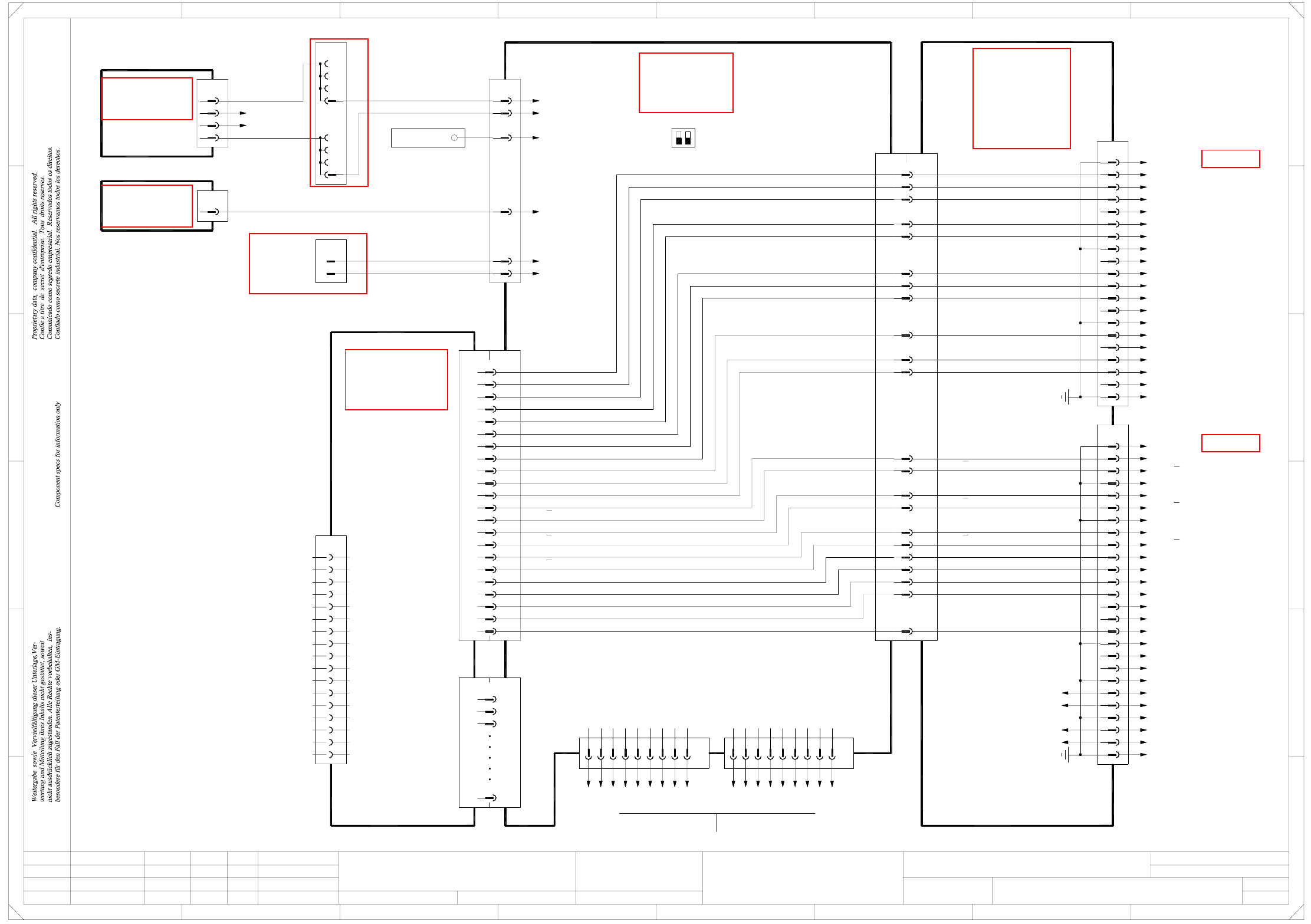
ZCP04_HF3-010201LD3 Z axis, Collect&Place head, gantry 4, HF/3 (Sh. 3 of 3)
20
18
19
17
15
16
X2vp
4
5
6
1
2
3
7
12
11
10
9
8
13
14
PE
n.u.
n.u.
n.u.
n.u.
n.u.
Flat ribbon cable
20x0.09mm²
n.u.
n.u.
Link voltage impressed
AGND
Inom W
Inom U
n.u.
Servo Ready
n.u.
Servo Enable -
Servo Enable +
A45 (vp)
Axis distributor I/O
00353487-xx
PE
1
20
19
17
18
16
14
15
13
7
10
11
12
8
9
4
6
5
3
2
X1vp
25
23
24
22
21
26
C10
C8
A2
A1
A8
A9
B3
A3
C7
C5
B5
B9
C9
X7vp
=
Date
Check.
Stand.
Author
Sheet
Orig. Repl. f. Repl. byNameDateModifiedStatus
Sh.
+
2
F
3
F
8
A
2
D
3
C
B
A
5
B
41
E
5
41
C
D
E
678
7
Z axis, Collect&Place head
Function st.
6
1.
2.
1.
09.02.04
22.09.05
22.09.05
09.02.2004
Hi
ZCP04_HF3-010201LD3
3
3
Hi
Hi
Hi
Product st.
Document st.
SIPLACE HF series
ZCP04_HF3-010201LD3_SH03.DWG
CAD file :
Mat. no. :
Servo Enable +
Servo Enable -
Servo Ready
Inom W
AGND
Inom U
Link voltage impressed
Sheet 1 / D2
Sheet 2 / E3
6
X10tq
3
5
4
2
1
-15V
+15V
GND
VCC
Power failure
Power failure
rd
bk
bk
dkbu
wh
pk
X33
Ground bus bar
DC/DC converter
00353450-xx
±15V
A18
2d
dkbu
dkbu
d22
X3wo
z20
2b
2c
pk
2a
X5wo
1d
1c
1A
1b
dkbu
Z4
d6
pk
pk
+15V axis
-15V axis
-15V / X21:19
+15V / X21:17
5V/15V
00353449-xx A17
DC/DC converter
X2wo
z16 rd VCC
X31
21 bk
12 bk
Power failure
Power failure
S1
ON
OFF
B4
A5
A4
C2
C1
B2
B1
A2
A1
Z track A
Z track N
Z track B
Z track N
Z track B
Z track A
A8
C8
A9
B3
CAN_H
CAN bus
1-Wire
GND
CAN_L
2
3
1
RESET
n.u.
9
8
Power failure
GND
GND
CAN_INT
7
6
5
4
CAN_L
1-Wire
CAN bus
3
2
1
C10
A3
C7
C5
B5
B9
C9
Link voltage impressed
Inom W
AGND
Inom U
Servo Ready
Servo Enable -
Servo Enable +
PE
PE
PE
PE
PE
PE
PE
PE
PE
PE
GND
03009834-xx
Act. value, Z1 axis
Gantry 4
GNDA28
GNDA28
Gantry 4
C&P head
C4
C4
Z sensor stop
Z sensor stop
+5V
+5V
HF/3
12
Axis unit Axis unit
A&D EA
s
4
03010051-xx
Power failure
RESET
8
9
n.u.
CAN_INT
CAN_H
GND
6
7
5
X30_1tq
X30_2tq
03010051-xx
Flat ribbon cable
B2
B1
C2
C1
A5
A4
B4
Z track A
Z track A
Z track B
Z track B
Z track N
Z track N
Z sensor stop
PE
+5V
n.u.
n.u.
n.u.
n.u.
n.u.
n.u.
n.u.
n.u.
n.u.
n.u.
Z track B
Z track N
Z track N
Z track B
Z track A
Z track A
X8tq
X8tqX2vb
X1vb
A/B/C1
X4tq
A/B/C32
A/B/C2
A/B/C3
SMP bus
A44 (tq)
Backplane, axis
00353485-xx
Z-axis axis board
A24 (vb)
00350575-xx
3
35
36
37
9
12
20
34
11
10
6
8
7
5
4
X3vb
2
1
VCC
-15V
+15V
TRIG
CAN_L
CAN_H
VREG
GND
INDEX
End signal
COUNT B
COUNT A
Inom
Vnom
RxD
TxD
AGND
See page 5-20
See page 5-19
See page 5-25
See page 5-27
See page 5-23
See page 5-13
See page 4-20
2 - 95
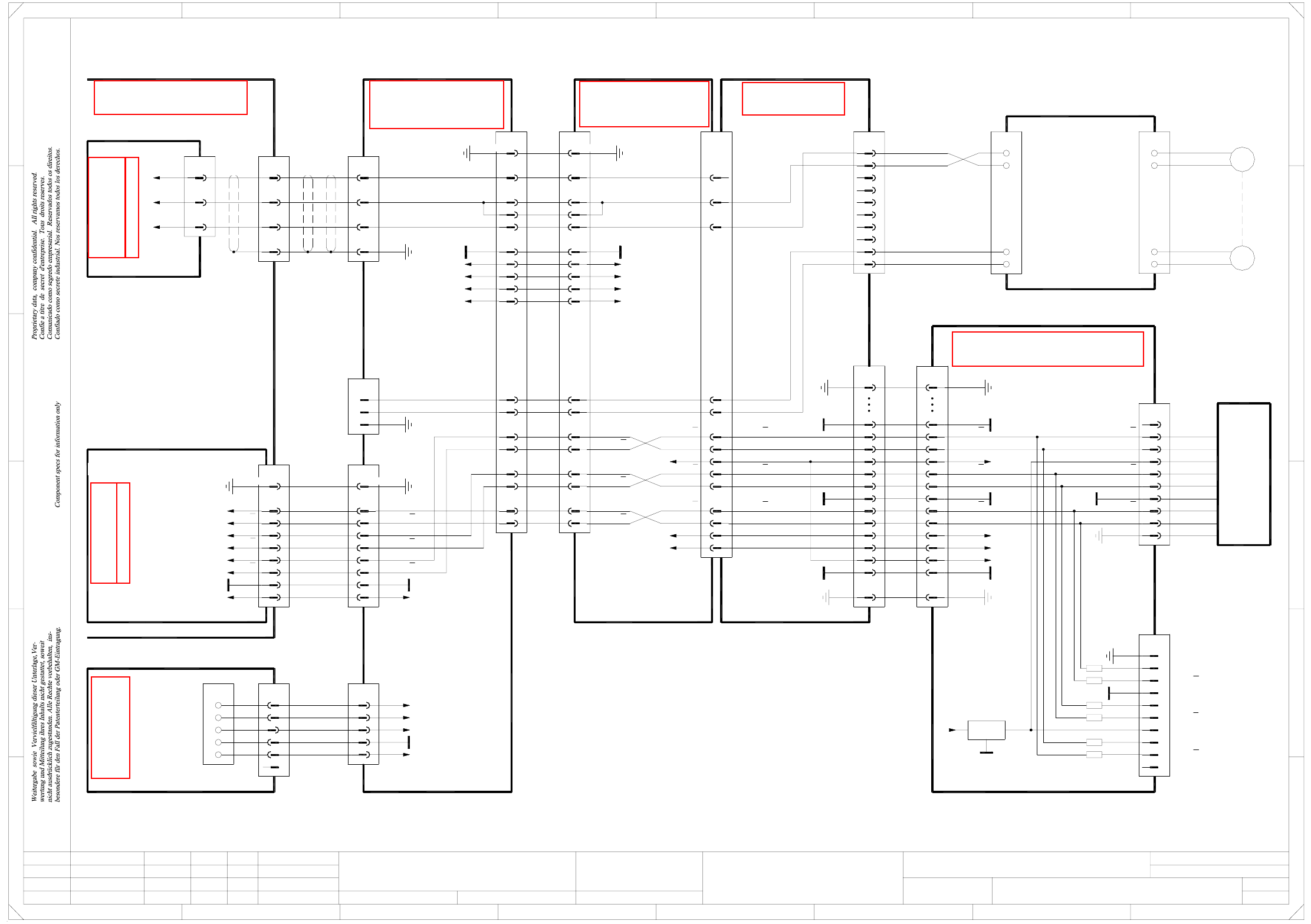
DPCP04_HF3-010201LD3 DP axis, Collect&Place head, gantry 4, HF/3 (Sh. 1 of 3)
=
Date
Check.
Stand.
Author
Sheet
Orig. Repl. f. Repl. byNameDateModifiedStatus
Sh.
+
2
F
3
F
8
A
2
D
3
C
A
5
B
41
E
5
41
C
D
E
DP axis, Collect&Place head
Function st.
s
A&D EA
678
76
1.
2.
1.
09.02.04
22.09.05
22.09.05
09.02.2004
Hi
DPCP04_HF3-010201LD3
1
3
Hi
Hi
Hi
Product st.
Document st.
SIPLACE HF series
DPCP04_HF3-010201LD3_SH01.DWG
CAD file :
Mat. no. :
Gantry 4
00330648-xx (ds)
SP6-12 intermediate distributor board, digital
DLM-X head adapter
03019066-xx (dq)
20
21
23
22
24
25
27
28
26
31
GND
DP track B
31
DP track B
DP track A
DP track A
26
28
27
25
24
22
23
21
20 DP track N
DP track N
X1ds
40
37
34
40
37
34
1919
AGND
PE
+15V
GNDGND
GND
7
10
8
9
1
4
5
6
2
3
X16ds
Track N
Track N
AGND
Track B
Track B
Track A
Track A
Test plug
X22dc/J3
100
102, 104
106
DP motor U
DP motor V
DP motor W
+15V
Head interface
03000901-xx (dc)
5
4
3
2
X8dc
1,10,14,34 PE
28
22
25
16, 31
DP motor U
DP motor V
DP motor W
GND
-15V
+15V
+24V
33
32
30
29
26
27 DP track N
DP track B
DP track A
DP track N
DP track B
DP track A
X8da
Cable carrier interface
03010622-xx (da)
Carrier cable 8
03013628-xx
DP1/DP2 motor
5
3
4
2
1,10,14,34
28
25
16, 31
22
+24V
+15V
-15V
GND
PE
27
26
29
30
32
33
X16da
1
2
3
4 PE
DP motor U
DP motor V
DP motor W
X26da
1,4,7,17,20,23,26
2
PE
3
5
6
10
8
9
GND
DP track N
X7ds
10
CP6: 00324968-xx
RSF digital encoder
CP12: 00335990-xx
n.u.
n.u.
6x470 Ω
PE
DP track N
DP track N
DP track B
DP track B
DP track A
DP track A
X14dq
1
PE AGND1
DP track A
DP track A
DP track B
DP track B
DP track N
DP track N
t
M
00321218-xx
5
6
7
8
Motor /tacho
DP axis
3
4
1
2
wh
bu
bk
rd
Interference suppression board
00330573-xx
DP motor
GND
7805
+15V
IN OUT
+5V
GND
+5V
HF/3
Flat ribbon cable
03004333-W1
+5V +5V
X161
2
3, 4
1
PE
DP tachom. -
DP tachom. +
GND
X2as:22
-15V
VCC
GND
+15V88, 90
-15V87, 89-15V
17
15
DP track A
DP track A
DP track B
DP track B
19
21
DP track N
DP track N23
25
VCC83, 85
VCC
DP tachom. +
DP tachom. -
29
27
23
24
DP tachom. -
DP tachom. +23
24
bu
wh
10
9
8
6
7
5
bk
rd
2
3
4
X12dq
1
Key
Key
DP tachom. +
DP tachom. -
DP motor +
DP motor -
4GND
1
+5V
2
3
7
5
6
8
9
DP track N
DP track B
DP track B
DP track A
DP track A
Track signals, DP axis
X50da
2
1
3
4
5 +5V
+15V
-15V
+24V
GND
DP1 motor
Cable carrier interface
03009825-xx
DP1 axis
Actual value
03009835-xx
36
37
38
35
X32
wh
gn
bn
bk bk
bn
gn
wh
3
2
X3tz
1
bk
rd
bn
bk
rd
bn
wh
03002164-W2
(Cable)
Gantries 2 or 4 Gantry 4
DP motor U
DP motor V
DP motor W
Servo ampl. backplane
DP axis / Collect&Place head
00353484-xx A42 (tz)
Axis unit
03016110-xx
X3vp
1,4,7,17,20,23,26
PE
2
3
5
6
8
9
10
GND
DP track N
DP track N
DP track B
DP track B
DP track A
DP track A
00353487-xx A45 (vp)
Axis distributor I/O
Sheet 3/D7
Cable carrier interface
03009828-xx W1/W2
(W1)wh
2
1
KEY
gn
bn
(W2)
(W2)
(W1)
(W1)
wh
or
X1ra_+24V
X1ra_+15V
X1ra_+5V
X1ra_0V
X1ra_-15V
pk
rd
bu
X1ra
1
4
6
5
3
2
X6ra
Voltage
Sub-distributor
03010005-xx (ra)
SIPLACE HF
Sheet 2 / E7
19+5V +5V19
12 12
See page 4-18
See page 5-22
See page 5-27
See page 5-58
See page 5-44
See page 5-61
See page 5-8
See page 4-8
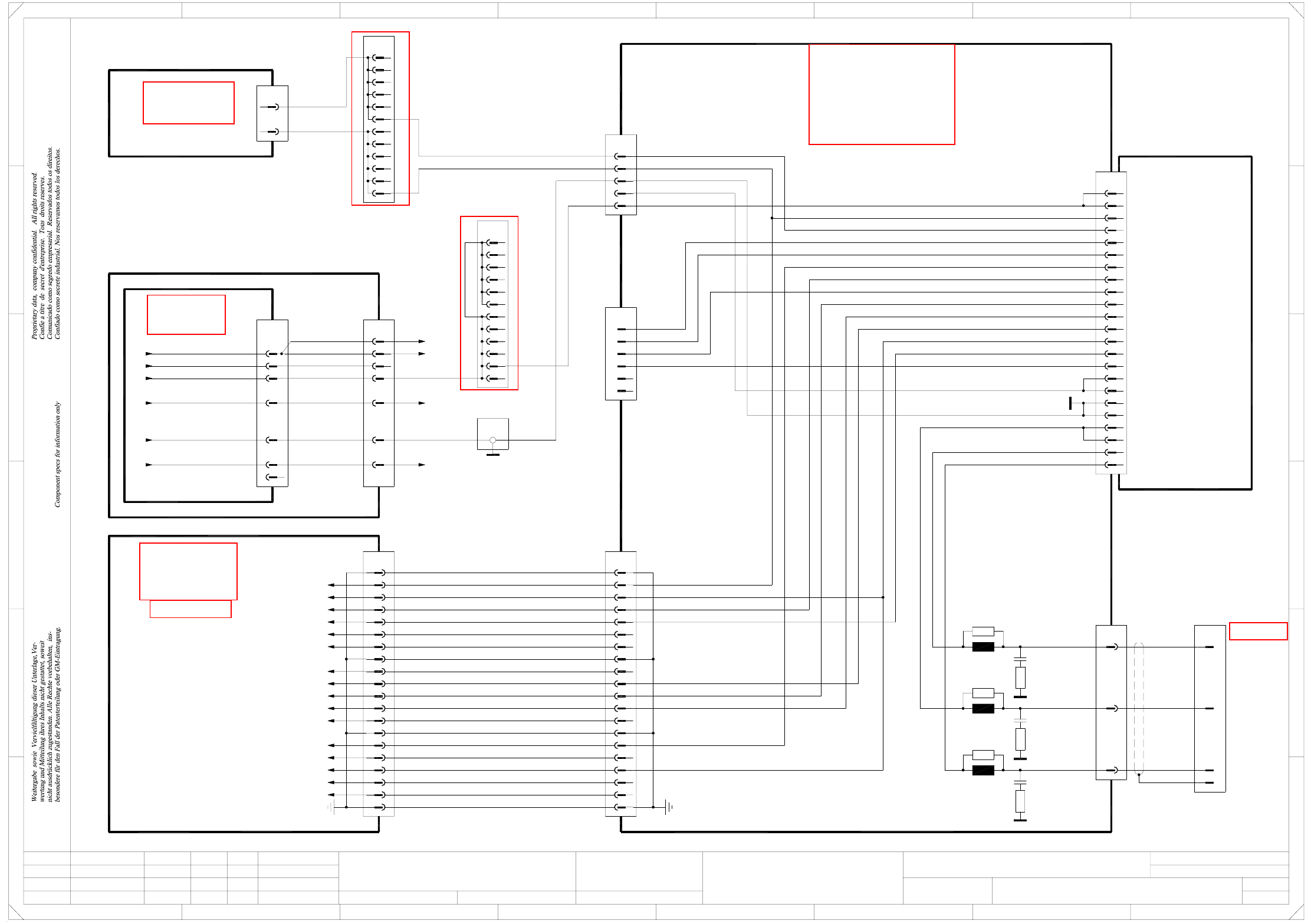
2 - 96
DPCP04_HF3-010201LD3 DP axis, Collect&Place head, gantry 4, HF/3 (Sh. 2 of 3)
=
Date
Check.
Stand.
Author
Sheet
Orig. Repl. f. Repl. byNameDateModifiedStatus
Sh.
+
2
F
3
F
8
A
2
D
3
C
B
A
5
B
41
E
5
41
C
D
DP axis, Collect&Place head
Function st.
s
A&D EA
E
678
76
1.
2.
1.
09.02.04
22.09.05
22.09.05
09.02.2004
Hi
DPCP04_HF3-010201LD3
2
3
Hi
Hi
Hi
Product st.
Document st.
SIPLACE HF series
DPCP04_HF3-010201LD3_SH02.DWG
CAD file :
Mat. no. :
18a
28a,c
32a,c
30a,c
20a,c
18c
26c
24a,c
22c
16c
12c
14c
12A
10c
X1tz
8c
10A
8A
6A
6c
Servo amplifier
SDS 60/1 D1
03002142-xx A16 (tz)
12
6
10
11
9
7
8
3
4
5
1
2
X2tz
6
X5tz
5
4
3
1
2
13
16
17
18
14
15
19
20
n.u.
n.u.
n.u.
n.u.
J²t
PE
Servo Enable +
Servo Enable -
Servo Ready
Inom W
AGND
Inom U
Link voltage impressed
ADR2
ADR1
ADR3
ADR4
X3tz
DP motor W
DP motor V
DP motor U
03002164-W2
(Cable)
20
18
19
17
15
16
X4vp
4
5
6
X23
X21
13
bn
Power supply
00354626-xx
X13
1
1
03009786-xx W1+W2
(Cable)
4c
4a
2a
2c
-15V
+15V
GND
ADR1
ADR2
ADR3
ADR4
Link voltage impressed
Servo Ready
AGND
Inom W
Inom U
Servo Enable
J²t
R31
L3
L2
R21
L1
R11
DP motor V
DP motor U
DP motor W
Gantry 4
C1
R12
R22
C2
R32
C3
Z/DP+ link voltage
Star+ link voltage
Star+
36
38
37
X32
35
bn
rd
bk
wh
vi
bu
or
wh
142
3
bn
vi11
PE
1
6
4
2
4
3
9
1
2
3
7
12
11
10
9
8
13
14
PE
Flat ribbon cable
20x0.09mm²
X5wo
3d
3e
3c
3b
3A
4a
4d
4b
4c
3f
4e
4f
A42 (tz)
00353484-xx
DP axis / Collect&Place head
Servo backplane
n.u.
n.u.
Link voltage impressed
AGND
Inom W
Inom U
n.u.
Servo Ready
n.u.
Servo Enable -
Servo Enable +
A45 (vp)
Axis distributor I/O
00353487-xx
1
2
3
00353449-xx
5V/15V
DC/DC converter
A17
X2wo
d6
d10
or +15V (Servo)
bu -15V (Servo)
Sheet 3 / B7
Sheet 1 / A2
n.u.
n.u.
n.u.
n.u.
n.u.
n.u.
n.u.
n.u.
X4tz
Z/DP+5
4
3
1
2
n.u.
n.u.
n.u.
n.u.
-15V
+15V
GND
bu
or
wh
n.u.
7
bk
wh
bk
16
25
23
n.u.
(W1)
(W1)
(W1)
(W1)
(W1)
(W2)
(W2)
gnye
Z/DP+ link voltage
Star+ link voltage
PE
Z/DP- link voltage
Vin_axis+
Vin_axis-
Z/DP+
X4tv:4
4e
4f
3e
4b
4d
4c
4a
3f
X4wo
3b
3d
3c
3A
X3wo:Z28, X2wo:Z28
X3wo:D30, X2wo:Z30
(DC/DC converter)
(DC/DC converter)
12
vi
X4sv:4
HF/3
vi
See page 5-19
See page 3-7
See page 5-27
See page 5-22
See page 5-25
See page 5-25