HF Circuit .pdf - 第247页
5 - 38 0036707 4-010 101ND4 Adjus tment u nit 2, p lacemen t circui t Mounting diagra m, component side Adjustment d rive 2 Plac eme nt circu it 00367 074-0 10101ND4 1 1 SIEMENS AG 06.11.2001 06.11.2001 01 St at. Mo di f…
5 - 37
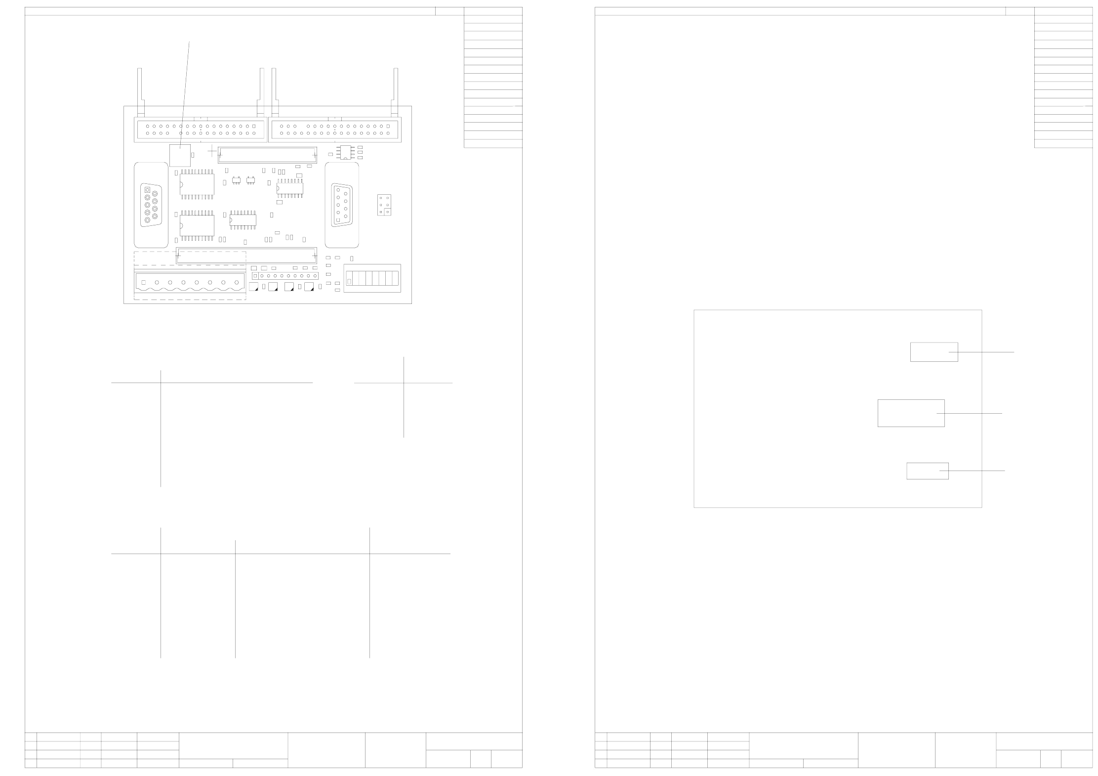
00363961-020101ND4 Vision control 1 (Sh. 1 of 2)
00363961-020101ND4 Vision control 1 (Sh. 2 of 2)
1
26.
5
8
7
6
543
2
1
ON
00363961-020101ND4
C1
Assembly Top
R52
X7
C1
U1
R25
R4
D2
C5
R33
D3
R3
R51
D4
R30
C7
R43
R34
U6
R31
R41
R32
C14
R16
X3
R50
X4
C15
D5
S1
X5
R6
R22
D1
R23
X2
R24
R42
R2
R48
R29
R1
X9
X1
R28
R38
R17
R5
C3
C4
C13
C8
U2
U4
C11
C6
R49
X6
C2
R14
R10
C9
X8
R12
R27
R37
C12
D6
U5
08.10.2002
81359 Muenchen
Rupert-Mayer-Strasse 44
A&D EA
Siemens
(Logo)
Legend
Layer(s):
J. Krueger
Document stat.
Product status
Function status
Released
Checked
Author
Date
Repl. by
Vision Control Unit 1
Repl. sie037.00-y1
ESD label
Total:
Page:
2
1
Prozessor module TQM167
X9 Voltage supply
Processor module TQM167
CAN bus
n.u.
X4 Flash signals
X5 CO camera, stationary, P&P (type 22) 50x40
X5 CO camera, stationary, P&P (type 20) 8x8
Assembly
X2
X9
X8
X5
X7
X3
X4
Connector
X1
1
0
01
0
0
0
0
0
8
7
6
5
4
3
2
HF (SW504)S1 switch HF (SW505) and HF/3
0
0
1
0
0
0
0
0
Main distributor
VoltageLED
D4
D3
D2
D1
+5 V
+40 V
-15 V
+15 V
pflichten zu Schadenersatz. Alle Rechte vorbehalten, ins
besondere für den Fall der Patenterteilung oder GM-Eintragung
wertung und Mitteilung ihres Inhalts nicht gestattet, soweit
Weitergabe sowie Vervielfältigung dieser Unterlage,Ver-
nicht ausdrücklich zugestanden. Zuwiderhandlungen ver-
Proprietary date, company confidential. All rights reserved.
Confie a titre de secret d'entreprise. Tous droits reserves.
Confiado como secrete industrial. Nos reservamos todos los derechos.
Comunicado como segredo empresarial. Reservados todos os direitos.
HF and HF/3
0
Sub-distributor
0
0
0
0
1
1
0
B2
A1
B1
Assembly Bottom
00363961-020101ND4
08.10.2002
81359 Muenchen
Rupert-Mayer-Strasse 44
A&D EA
Siemens
(Logo)
Legend
Layer(s):
J. Krueger
Vision Control Unit 1
Repl. sie037.00-y1
Repl. by
Document stat.
Product status
Function status
Date
Author
Checked
Released
Inspection label "AFO"
Identification label
Inspection label "WIP"
Page:
Total:
2
2
pflichten zu Schadenersatz. Alle Rechte vorbehalten, ins
besondere für den Fall der Patenterteilung oder GM-Eintragung
wertung und Mitteilung ihres Inhalts nicht gestattet, soweit
Weitergabe sowie Vervielfältigung dieser Unterlage,Ver-
nicht ausdrücklich zugestanden. Zuwiderhandlungen ver-
Proprietary date, company confidential. All rights reserved.
Confie a titre de secret d'entreprise. Tous droits reserves.
Confiado como secrete industrial. Nos reservamos todos los derechos.
Comunicado como segredo empresarial. Reservados todos os direitos.
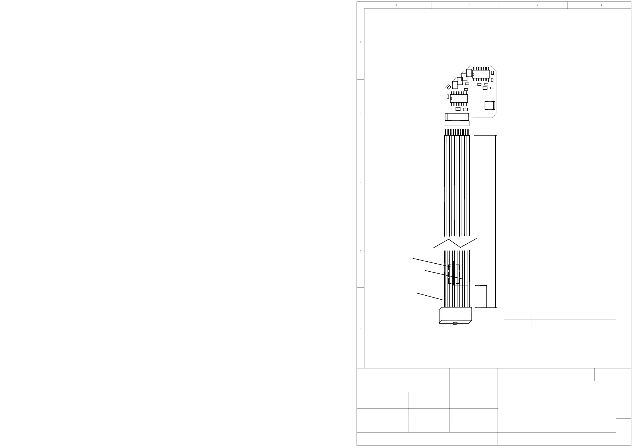
5 - 38
00367074-010101ND4 Adjustment unit 2, placement circuit
Mounting diagram, component side
Adjustment drive 2
Placement circuit
00367074-010101ND4
1
1
SIEMENS AG
06.11.2001
06.11.200101
Stat. Modified Date Name
Date
Name
Sheet
Sh.
U1
X1
R5
R6
Pin 1
X1
A1
B1, B2
1
10
R
1
X2
C3
X3
R4
U2
X5
X4
R2
R3
+5.0mm
-5.0mm
50.0mm
340.0mm
B1, B2:
A1:
C2
U3
R7
C4
C5
C6
Cable, 05-1630-5
X18 stepping motor board 00344488
Assembly
Connector
X1
on the cable
Readable, when X1 is on the right.
50mm distance from cable end.
AFO and WIP inspection labels.
Label position:
On the back.
Identification label,
readable, when X1 is on the left.
May be printed
pflichten zu Schadenersatz. Alle Rechte vorbehalten, ins
besondere für den Fall der Patenterteilung oder GM-Eintragung
wertung und Mitteilung ihres Inhalts nicht gestattet, soweit
Weitergabe sowie Vervielfältigung dieser Unterlage,Ver-
nicht ausdrücklich zugestanden. Zuwiderhandlungen ver-
Proprietary date, company confidential. All rights reserved.
Confie a titre de secret d'entreprise. Tous droits reserves.
Confiado como secrete industrial. Nos reservamos todos los derechos.
Comunicado como segredo empresarial. Reservados todos os direitos.
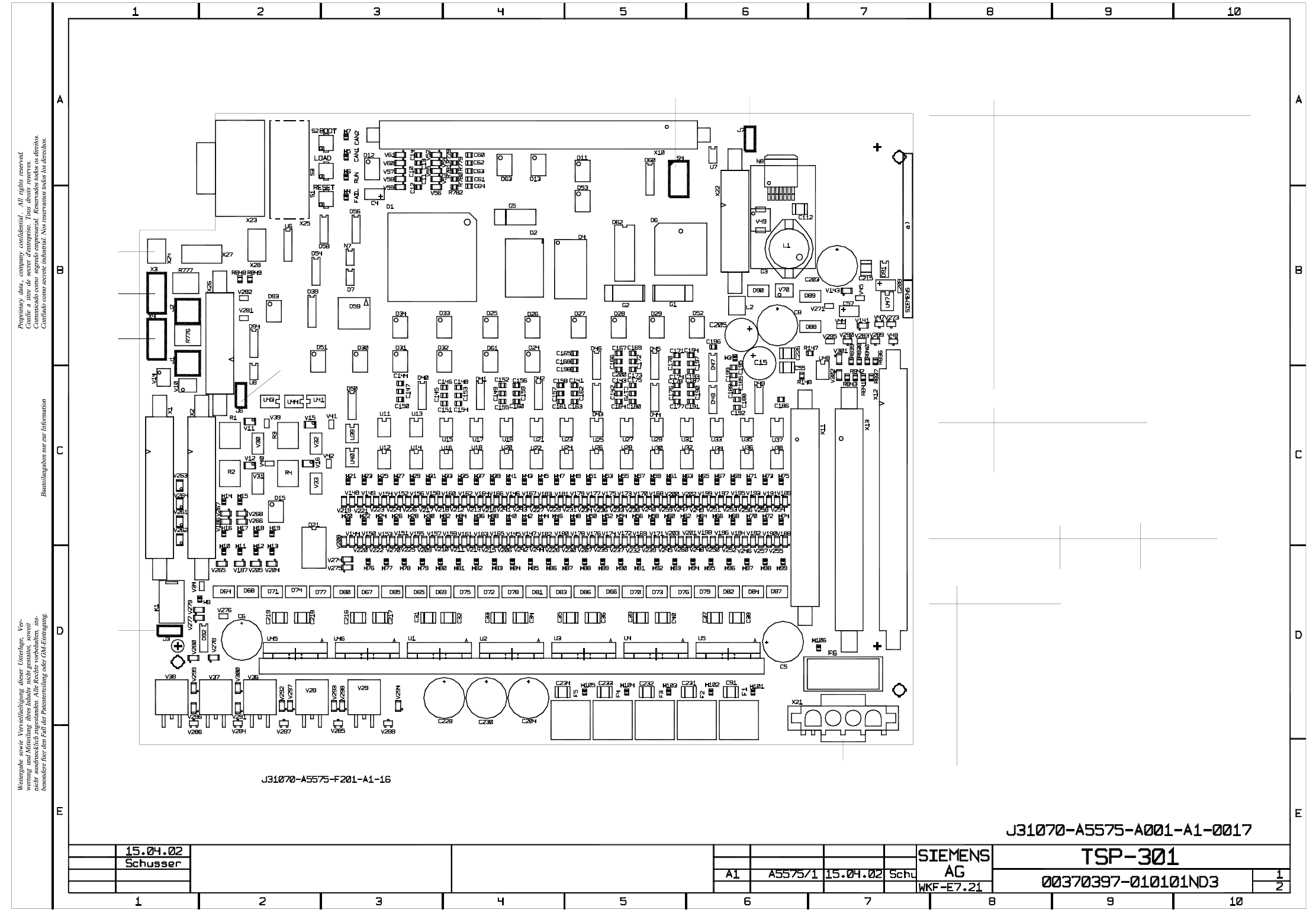
5 - 39
00370397-010101ND3 TSP 301 (Sh. 1 of 2)
Date
Author
Check.
Stand.
Placement diagram
SMD and components with axial leads
Side 1
Stat. Modified Date
Name
Position for identification label
on side 1
a)
X3
X3
X4
J2
J1
J6
X1 X2
J3
S4 J7
X22
AssemblyConnector
X1
X2
X3
X4
X10
X11
X12
X13
X22
X23
X24
X25
X26
X21
X21:1
X21:2
X21:3
X21:4
Siemens interface, upstream station, conveyor track 1
Siemens interface, downstream station, conveyor track 1
SMEMA interface, upstream station, conveyor track 1
SMEMA interface, downstream station, conveyor track 1
Bus cable to TSP 300E
Conveyor motors, "width adjustment" motor
Sensors/actors
Sensors/actors
Power supply
n.u.
n.u.
RS232 Boot/Debug
GND
CAN bus
CAN bus
n.u.
34 VDC to 42 VDC
24 VDC
Assembly
Fault loop 1-2
CAN bus, pins 2-3
CAN bus, pins 1-2
Jumper
J7
J3
J6
Sh.
Sh.
SIEMENS SMEMA
1-2, 4-5, 7-8 2-3, 5-6, 8-9J1
2-3, 5-6, 8-91-2, 4-5, 7-8J2
J1/J2 interface jumpers, conveyor track 1
Downstream station
Upstream station
Distributor, PCB barcode scanner
X27
F6
X11
X13
X12
X10
X23 X25
X24
X27
X26
F5 F4 F3 F2 F1
X21
S4
OFF
OFF
OFF
OFF
OFF
ON
OFF
ON
2
8
5
6
7
4
3
1
3
OFF from machine no. 56:
up to machine no. 55:
clamping detection via clamping sensor
clamping detection via motor current measurement