5965-4792.pdf - 第13页
1 6 0 4 7E T es t fix ture T erminal connector : 4- T er minal P air , BNC DUT connec tion: 2 -Te r m i n a l Dimensions ( appr o x.): 1 35 ( W ) x 4 0 (H) x 65 (D) [ mm] Wei gh t (ap pr ox .): 2 0 0 g Additional error :…
Up to 120 MHz (4-Terminal Pair): Lead Components
16047A Test fixture
Terminal connector: 4-Terminal pair, BNC
DUT connection: 4-Terminal
Dimensions (approx.):
124 (W) x 31 (H) x 62 (D) mm
Weight (approx.): 205 g
Additional error:
f: [MHz]
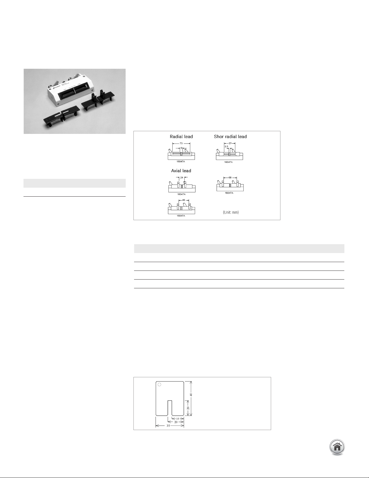
Description: This test fixture is designed for impedance evaluation of axial/radial lead
type devices. The 16047A employs Kelvin contacts which realize a wide impedance
measurement range. The contact tip can be changed according to the device shape.
Applicable instruments: E4980A/AL, E4981A, E4990A
Frequency: DC to 13 MHz
Maximum voltage: ±42 V peak max. (AC+DC)
Operating temperature: 0 to 55°C
DUT size: See figure with module sizes.
Furnished accessories:
Each module size for the 16047A is shown above.
Option:
16047A-701: Add Shorting plate P/N 16047-00640
Compensation and measurement: Select one of these modules suitable for the DUT’s
shape. Open and short compensations are recommended before measurement. Short
compensation is performed by shorting the contacts of the test fixture with a shorting
plate. After performing open and short compensations, the DUT is connected to the test
fixture.
16047A module sizes
Shorting plate
P/N 16047-00640
Material:
Brass (Ni-dipped)
Thickness:
1.0 mm
Residual impedance:
20nH, 1mΩ
Description P/N Qty.
Module for axial lead 16061-70022 2
Module for radial lead mounting on fixture 16061-70021 2
Module for short radial lead 16047-65001 2
Operating note 16047-90011 1
Type of error Impedance
Proportional error ±5 x (f/10)
2
09 | Keysight | Accessories Catalog for Impedance Measurements - Catalog
16047E Test fixture
Terminal connector: 4-Terminal Pair, BNC
DUT connection: 2-Terminal
Dimensions (approx.):
135 (W) x 40 (H) x 65 (D) [mm]
Weight (approx.): 200 g
Additional error:
f: [MHz]
Up to 120 MHz (4-Terminal Pair): Lead Components continued
Test fixture overview
Connecting a shorting plate
Measuring 3-Terminal device
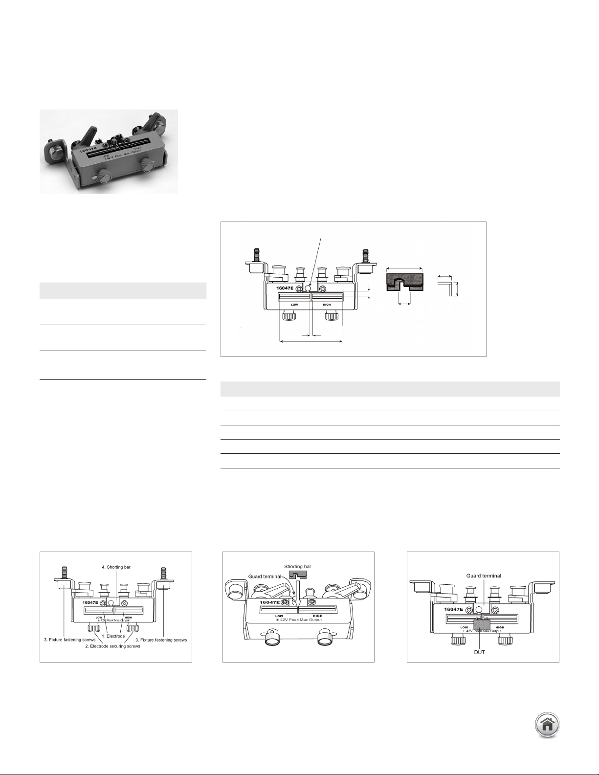
Description: This test fixture is designed for impedance evaluation of lead type devices
up to 120 MHz. A guard terminal is available for three terminal devices and a shorting
plate comes secured on this fixture.
Applicable instruments: E4980A/AL, E4981A, E4990A, E5061B-3L3/3L4/3L5
with Opt. 005
Frequency: DC to 120 MHz
Maximum voltage: ±42 V peak max.(AC+DC)
Operating temperature: –20 to 75°C
DUT size: See figure below with 16047E’s electrode size.
Furnished accessories:
Compensation and measurement: Open and short compensations are recommended
before measurement. Short compensation is performed by shorting the contacts of the
test fixture with a shorting plate. After performing open and short compensations, the
DUT is connected to the test fixture. The following figures show how compensation and
measurement are performed.
Guard terminal
Shorting plate
(furnished)
Top view Side view
14 mm
2 mm
9.3 mm
5.3 mm
1.6 mm
62 mm
±42 V Peak max output
10 mm
Type of error Impedance
Proportional error
f ≤ 15 MHz
0.2 x (f/10)
2
[%]
Proportional error
f > 15 MHz
4 x (f/100)[%]
Open repeatability 2 n+10 µ x (f/100) [S]
Short repeatability 2 m+600 m x (f/100) [Ω]
Description P/N Qty.
Angle (right-side) 16047-01221 1
Angle (left-side) 16047-01222 1
Screws 0515-1229 4
Shorting plate 16047-00621 1
Operating and service manual 16047-90040 1
10 | Keysight | Accessories Catalog for Impedance Measurements - Catalog
16034E Test fixture
Terminal connector: 4-Terminal Pair, BNC
DUT connection: 2-Terminal
Dimensions (approx.):
128 (W) x 60 (H) x 71 (D) [mm]
Weight (approx.): 270 g
Additional error:
f: [MHz]
Up to 120 MHz (4-Terminal Pair): SMD
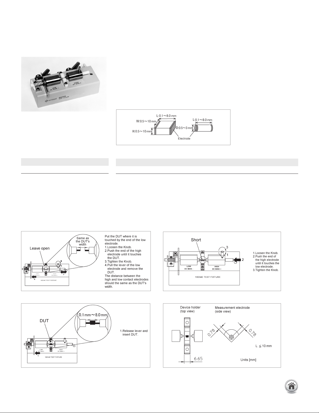
Description: This test fixture is designed for impedance evaluations of SMD. The
minimum SMD size that this fixture is adapted to evaluate is 1.6(L) x 0.8(W) [mm].
Applicable instruments: E4980A/AL, E4981A, E4990A, E5061B-3L3/3L4/3L5
with Opt. 005
Frequency: DC to 40 MHz
Maximum voltage: ±42 V peak max. (AC+DC)
Operating temperature: 0°C to 55°C
DUT size: See figure below
Furnished accessories:
Compensation and measurement: Open and short compensations are recommended
before measurement. Open compensation is performed by separating the high and low
electrodes from each other. The separation should be equivalent in size to the DUT’s
width. Short compensation is performed by contacting the high and low electrodes
together. After performing open and short compensations, the DUT is inserted into
the test fixture. The following figures show how compensation and measurement are
performed.
Open compensation
Short compensation
Inserting a DUT
Electrode dimensions
Description P/N Qty.
Operating manual 16034-90041 1
Type of error Impedance
Proportional error ±1.5 x (f/10)
2
11 | Keysight | Accessories Catalog for Impedance Measurements - Catalog