5965-4792.pdf - 第35页
1 61 9 4 A High temp era - ture com ponent test f ix ture T erminal connector : 7 mm DUT connec tion: 2 -Te r m i n a l Elec trical leng th: 50 mm Dimensions ( appr o x.): 1 5 0 (W ) x 4 0 (H) x 80 (D) [ mm] Wei gh t (ap…
Up to 3 GHz (7 mm): SMD continued
Options:
16192A-010: Add EIA/EIAJ industrial standard sized shorting bar set
16192A-701: Add general sized shorting bar set
16192A-710: Add the magnifying lens and tweezers
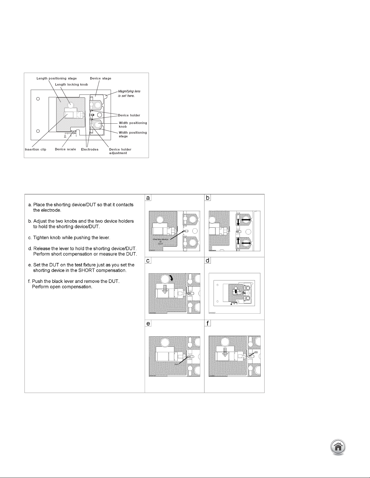
Compensation and measurement: Open and short compensations are
recommended in combination with the electrical length compensation before
measurement. The fixture’s electrical length must be entered into the electrical
length compensation function of the measurement instrument first. Then open
compensation is performed by separating the high and the low electrodes from
each other. The separation should be equivalent in size to the DUT’s width. Short
compensation is performed by using option 16192A-010/701 shorting bar set.
After performing open and short compensations in combination with the electri-
cal length compensation, the DUT is inserted into the test fixture. The following
figures show how compensation and measurement is performed.
Test fixture overview
Open/short compensation
For more details, please refer
to 16192A operation manual.
16192A Parallel electrode SMD test fixture continued
31 | Keysight | Accessories Catalog for Impedance Measurements - Catalog
16194A High tempera-
ture component test fixture
Terminal connector: 7 mm
DUT connection: 2-Terminal
Electrical length: 50 mm
Dimensions (approx.):
150 (W) x 40 (H) x 80 (D) [mm]
Weight (approx.): 350 g
Additional error:
SMD:
Leaded device:
f: [GHz]
Up to 3 GHz (7 mm): SMD continued
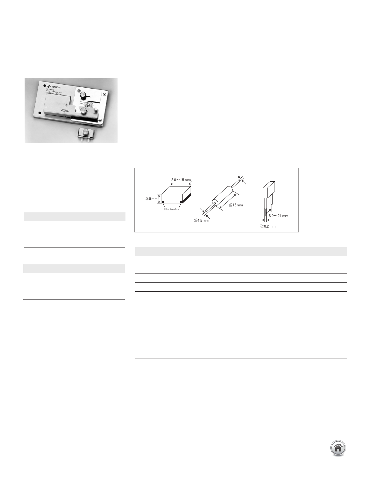
Description: This test fixture is designed for measuring both axial/radial leaded devices
and SMD within the temperature range from –55 to +200 °C (when used with the
E4991B-007 Temperature Characteristic Test Kit, –55 to +150 °C).
Applicable instrument: E4982A, E4990A + 42942A*, E4991B, E5061B-3L3/3L4/3L5
with Opt. 005 + 16201A
* Option E4990A-120 is required
Frequency:
DC to 500 MHz (with open and short compensation)
DC to 2 GHz (with open and short and load compensation)
Maximum voltage: ±42 V peak max. (AC+DC)
Operating temperature: –55 to +200°C
DUT size: See figure below.
Type of error Impedance
Proportional error 20 x f
2
[%]
Open repeatability 80 + 250 x f [
µ
S]
Short repeatability 0.2 + 2.5 x f [Ω]
Type of error Impedance
Proportional error 20 x f
2
[%]
Open repeatability 80 + 500 x f [
µ
S]
Short repeatability 0.4 + 12.5 x f [Ω]
Description P/N Qty. Option
Wrench 8710-1181 1 Standard
Tweezers 8710-2081 1 Standard
50Ω SMD resistor 0699-2829 10 Standard
Operation and service manual 16194-90030 1 Standard
General sized
Shorting device
(1 x 1 x 2.4 (mm))
Shorting device
(1.6 x 2.4 x 2 (mm))
Shorting device
(2.4 x 2.4 x 3.2 (mm))
Shorting device
(2.4 x 2.4 x 4.5 (mm))
16191-29001
16191-29002
16191-29003
16191-29004
1
1
1
1
16192A-701
16192A-701
16192A-701
16192A-701
EIA/EIAJ industrial standard sized
Shorting device
(1 x 0.5 x 0.5 (mm))
Shorting device
(1.6 x 0.8 x 0.8 (mm))
Shorting device
(2.0 x 1.2 x 0.8 (mm))
Shoring device
(3.2 x 1.6 x 0.8 (mm))
16191-29005
16191-29006
16191-29007
16191-29008
1
1
1
1
16192A-010
16192A-010
16192A-010
16192A-010
Case for shorting devices 1540-0692 1 16192A-010/701
Furnished accessories:
32 | Keysight | Accessories Catalog for Impedance Measurements - Catalog
Up to 3 GHz (7 mm): SMD continued
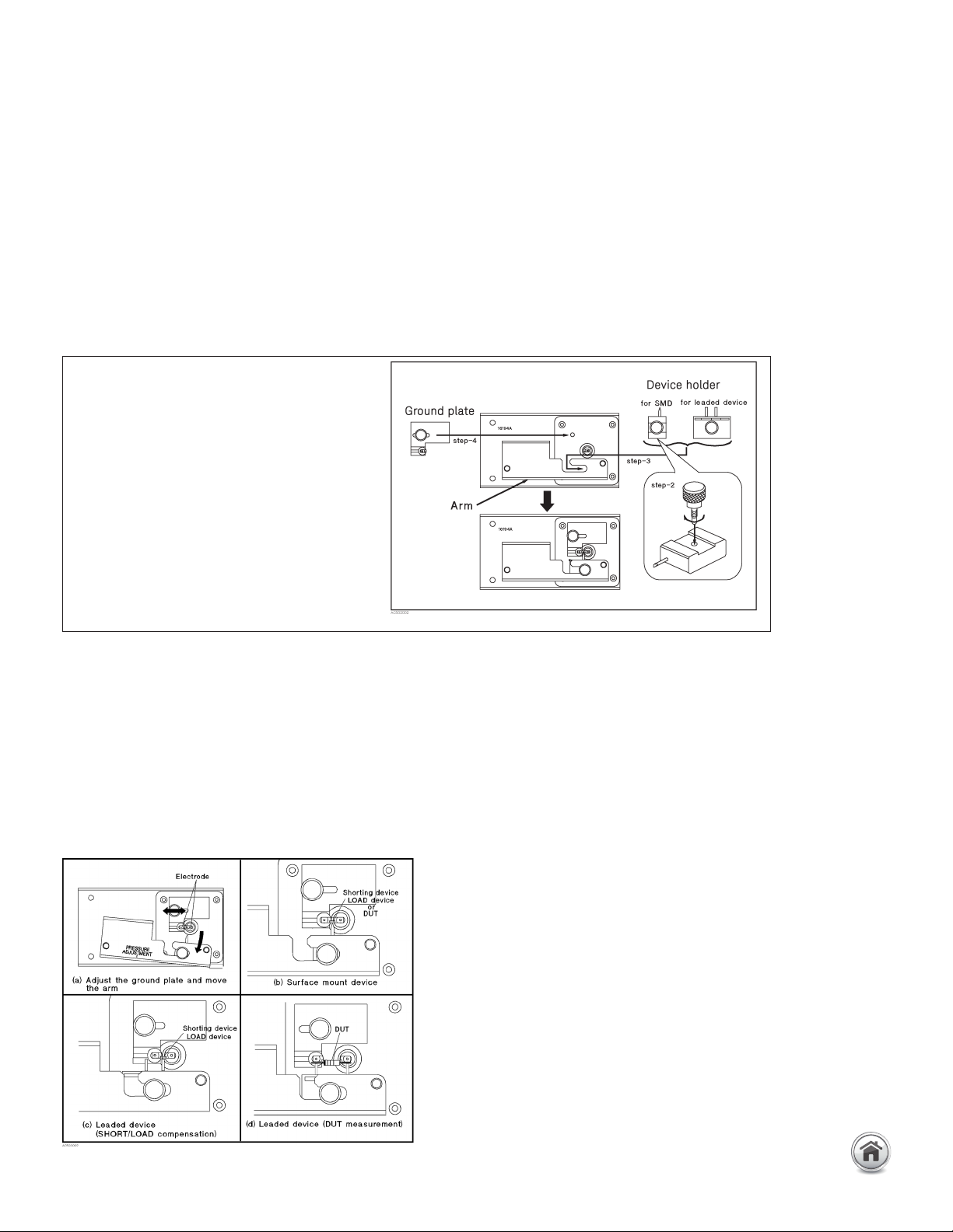
Exchanging the device holder
1. Remove the ground plate
2. When measuring SMD, attach the
knob on the device holder.
3. Select the device holder suitable for
the device type. Loosen its knob and
insert into the arm.
4. Set the ground plate.
Placing the device
16194A High temperature component test fixture continued
Options:
16194A-010: Add EIA/EIAJ industrial standard sizedshorting bar set
16194A-701: Add general sized shorting bar set
Compensation and measurement: Before beginning the measurement, the appropriate
device holder (for a SMD or lead component) must be prepared with the text fixture. The
following figure shows how the device holder is exchanged to match the device type.
The next step is to perform open and short compensations in combination with the
electrical length compensation. When measuring above 500 MHz, load compensation
is also recommended. The fixture’s electrical length must be entered into the electrical
length compensation function of the measurement instrument first. Then open com-
pensation is performed by separating the high and the low electrodes from each other.
The separation should be equivalent in size to the DUT’s width. Short compensation is
performed by using the option 16194A-010/701 shorting bar set. Load compensation is
performed by using the furnished 50 Ω SMD chip resistor. After performing open, short,
and load compensations in combination with the electrical length compensation, the
DUT is inserted into the test fixture. The following figures show how measurement is
performed.
33 | Keysight | Accessories Catalog for Impedance Measurements - Catalog