5965-4792.pdf - 第50页
Optional accessorie s P/ N Con ta ct bo ard (Guide P CA 0 201, 70 microm eter) 1 6 1 9 8 A -1 0 1 Con ta ct bo ard (Guide P CA 0 201, 1 0 0 microm eter ) 16 1 9 8 A -1 0 2 Con ta ct bo ard (Guide P CA 0 4 02 , 1 0 0 micr…
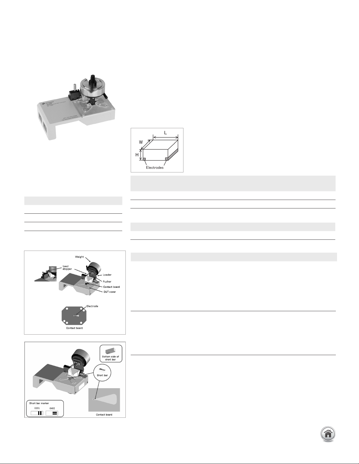
16198A Bottom electrode SMD
test fixture
Terminal connector: 7 mm
DUt connection: 2-Terminal
Dimensions (approx.):
145 (W) × 80 (D) × 110 (H) [mm]
Weight (approx.): 870 g (with weight of
300 g)
Additional error:
Description: This test fixture is designed for impedance evaluations of bottom electrode
SMDs. It achieves stable frequency characteristics up to 3 GHz and provides highly
repeatable measurements. This test fixture supports two SMD sizes, 0201 (mm)/
008004 (inch) and 0402 (mm)/01005 (inch).
Applicable instrument: E4982A, E4991B, E5061B-3L3/3L4/3L5 with Opt. 005 + 16201A
Frequency: DC to 3 GHz
Maximum voltage: ±40 V peak max. (AC +DC)
Operating temperature: –55 to +85°C
DUT size: See figure and table below:
Standard option
SMD size code
Applicable SMD size
L [mm] W [mm] H [mm]
0402 (mm)/01005 (inch) (0.38 to 0.42) ±0.02 (0.18 to 0.22) ±0.02 ≥ 0.11
0201 (mm)/008004 (inch) (0.2 to 0.25) ±0.013 (0.1 to 0.125) 0.013 ≥ 0.1
Furnished Accessory
Description P/N
Cleaning rod 5182-7586
f: frequency [GHz]
Up to 3 GHz (7 mm): SMD continued
Error factor Formula
Proportional error 1.2 x f
2
[%]
Open repeatability 5 + 40 x f [μS]
Short repeatability 60 + 125 x f [mΩ]
Optional accessories
Standard set P/N Qty.
Standard set, 0201 16198A-100
Contact board (Guide PCA 0201 70 micrometer) 1
Contact board (Guide PCA 0201 100 micrometer) 1
0201 Short bar 5-piece set 1
Weight 50 g 1
Weight 100 g 1
Weight 200 g 1
Standard set, 0402 16198A-200
Contact board (Guide PCA 0402 100 micrometer) 1
0402 Short bar 5-piece set 1
Weight 50 g 1
Weight 100 g 1
Weight 200 g 1
Note: A standard set of either 0201 or 0402 can be ordered, but not both.
If necessary, the parts can be ordered individually.
46 | Keysight | Accessories Catalog for Impedance Measurements - Catalog
Optional accessories P/N
Contact board (Guide PCA 0201, 70 micrometer) 16198A-101
Contact board (Guide PCA 0201, 100 micrometer) 16198A-102
Contact board (Guide PCA 0402, 100 micrometer) 16198A-201
0201 Short bar 5-piece set 16198A-110
0402 Short bar 5-piece set 16198A-210
Weight 50 g 16198A-520
Weight 100 g 16198A-521
Weight 200 g 16198A-522
Carrying case 16198A-530
Torque driver 16198A-531
User manual English 16198A-ABA
User manual Japanese 16198A-ABJ
Retrofit/service parts P/N
Contact board (Guide PCA 0201, 70 micrometer) 16198AU-101
Contact board (Guide PCA 0201, 100 micrometer) 16198AU-102
Contact board (Guide PCA 0402, 100 micrometer) 16198AU-201
Contact board 8-piece set (Guide PCA 0201, 70 micrometer) 16198AU-103
Contact board 8-piece set (Guide PCA 0201, 100 micrometer) 16198AU-104
Contact board 8-piece set (Guide PCA 0402, 100 micrometer) 16198AU-202
0201 Short bar 5-piece set 16198AU-110
0402 Short bar 5-piece set 16198AU-210
Weight 50 g 16198AU-520
Weight 100 g 16198AU-521
Weight 200 g 16198AU-522
Carrying case 16198AU-530
Torque driver 16198AU-531
Pusher unit 16198AU-540
DUT cover ass’y 16198AU-544
Connector APC3.5 16198AU-545
Up to 3 GHz (7 mm): SMD continued
16198A Bottom electrode SMD test fixture continued
47 | Keysight | Accessories Catalog for Impedance Measurements - Catalog
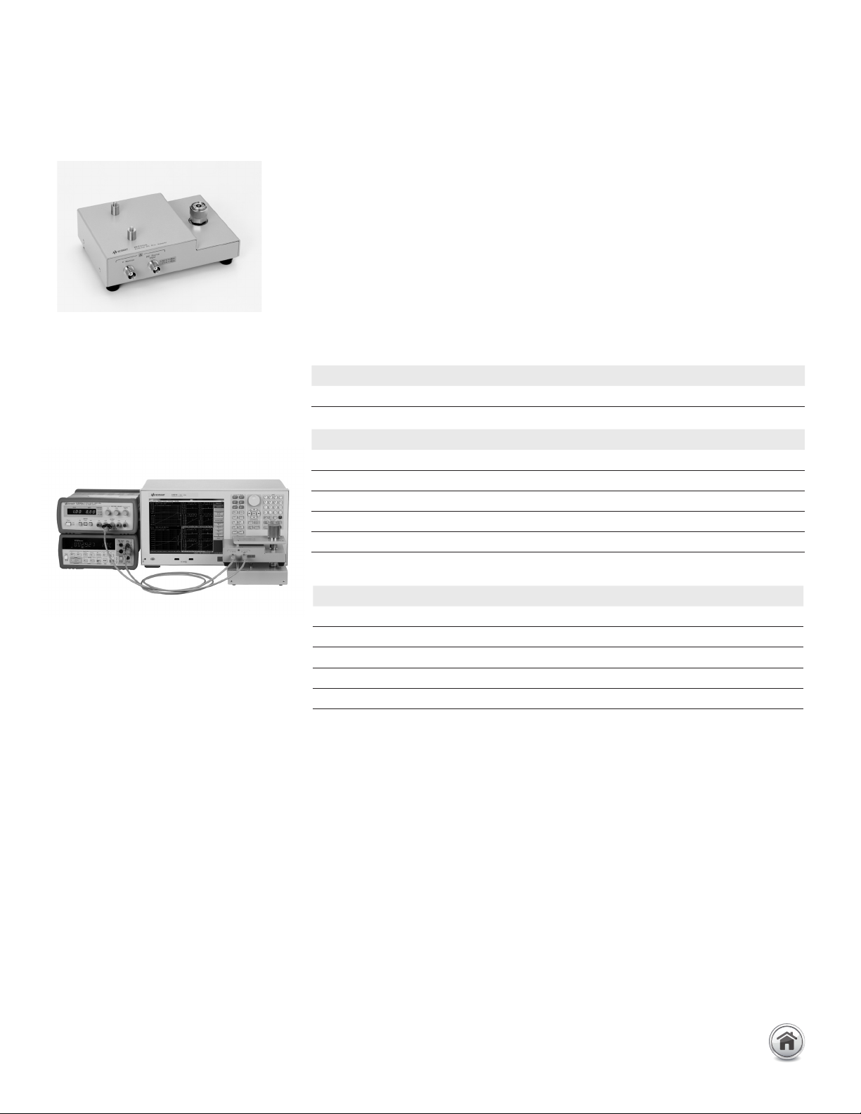
16200B external DC bias adapter
Terminal connector: 7 mm
DC BIAS input connector: BNC(f)
Voltage monitor connector: BNC(f)
Dimensions (approx.):
170 (W) x 70 (H) x 130 (D) [ mm]
Weight (approx.): 900 g
Up to 3 GHz (7 mm): DC Bias Accessories
Description: This test fixture is designed to measure a DUT with DC bias. By connecting
an external DC current source to the 16200B, it can supply a bias current across the
DUT of up to ±5 Adc through a 7 mm port.
Applicable instruments: E4982A, E4990A + 42942A*, E4991B, E5061B-3L3/3L4/3L5
with Opt. 005 + 16201A
* Option E4990A-120 is required
Frequency: 1 MHz to 1 GHz
DC bias: Up to 5A, 40 V (Input)
Operating temperature: 0 to 55°C
Applicable fixtures: 16192A, 16194A, 16196A/B/C/D, 16197A, 16092A
Furnished accessories:
16200B-001 Shorting device set
16200B-001 Load device set
Options:
16200B-001: Add Working std set
Compensation and measurement: When using the 4291B, follow these instructions:
Perform open, short, load and low-loss calibration at the 7 mm test port of the 4291B.
Connect the 16200B to the 7 mm test port, and connect the test fixture onto the
16200B. Open, short, and load compensations are recommended before measurement.
Use the short bars and 51 Ω SMD resistors furnished with 16200B-001 to perform short
and load compensation respectively.
When using other instruments, follow these instructions:
Connect the 16200B to the 7 mm test port of the measurement instrument. Perform
open, short, load (and low-loss calibration) at the 7 mm test port of the 16200B. Then,
connect the test fixture onto the 16200B and perform open, short, and electrical length
compensations in the usual manner.
Connection example
Description P/N Qty.
Operation and service manual 13200-90011 1
Size P/N Qty.
0.6 x 0.3 x 0.3 (mm) 16197-29001 2
1 x 0.5 x 0.5 (mm) 16191-29005 2
1.6 x 0.8 x 0.8 (mm) 16191-29006 2
2.0 x 1.2 x 0.8 (mm) 16191-29007 2
3.2 x 1.6 x 0.8 (mm) 16191-29008 2
Size P/N Qty.
0.6 x 0.3 x 0.3 (mm) 0699-6926 5
1 x 0.5 x 0.5 (mm) 5182-0433 5
1.6 x 0.8 x 0.8 (mm) 5182-0434 5
2.0 x 1.2 x 0.8 (mm) 5182-0435 5
3.2 x 1.6 x 0.8 (mm) 5182-0436 5
48 | Keysight | Accessories Catalog for Impedance Measurements - Catalog