5965-4792.pdf - 第46页
1 61 97 A Bot tom e lectrode SM D test f ix ture T erminal connector : 7 mm DUt connec tion : 2 -Te r m i n a l Elec trical leng th: 1 4 mm Dimensions ( appr o x.): 1 6 0 ( W) x 70 (H) x 8 6 (D) [ mm] Wei gh t (ap pr ox …

16196D Parallel electrode SMD test fixture continued
Options:
16196D-710: Add the magnifying lens and tweezers
To maintain adequate measurement performance, keep the electrodes and the short
plate in good condition. Contaminants and abrasion on these parts considerably affect
measurement results, especially for low value measurements. Periodic fixture cleaning
and part replacement is recommended to avoid deterioration of measurement perfor-
mance. The 16196x fixtures are designed with simplicity in mind, so that an operator can
easily replace parts. Spare parts, which are likely to be abraded, are supplied with the
16196U Maintenance Kit.
16196U Maintenance kit
Opt. 16196U-020: Upper electrode, 5 piece set for 16196D
Opt. 16196U-400: Short plate for 01005 (inch)/0402 (mm) size, 5 piece set (for 16196D)
Opt. 16196U-410: Lower electrode, 5 piece set (for 16196D)
Compensation and measurement: First of all, install the appropriate insulator as-
sembly into the fixture. Then, perform compensation. Open and short compensations
are recommended in combination with the electrical length compensation before
measurement. The fixture’s electrical length must be entered into the electrical length
compensation function of the measurement instrument first. Next, open compensation
is performed by placing the furnished open plate on top of the insulator assembly.
Short compensation is performed by placing the furnished shorting plate on top of the
insulator assembly. After performing open and short compensations in combination with
the electrical length compensation, the DUT is inserted into the test fixture. Once the
measurement of the DUT is complete, remove the DUT from the fixture, by using the
furnished push ring. Refer to the 16196A figures to see how compensation and measure-
ment is performed.
Up to 3 GHz (7 mm): SMD continued
42 | Keysight | Accessories Catalog for Impedance Measurements - Catalog
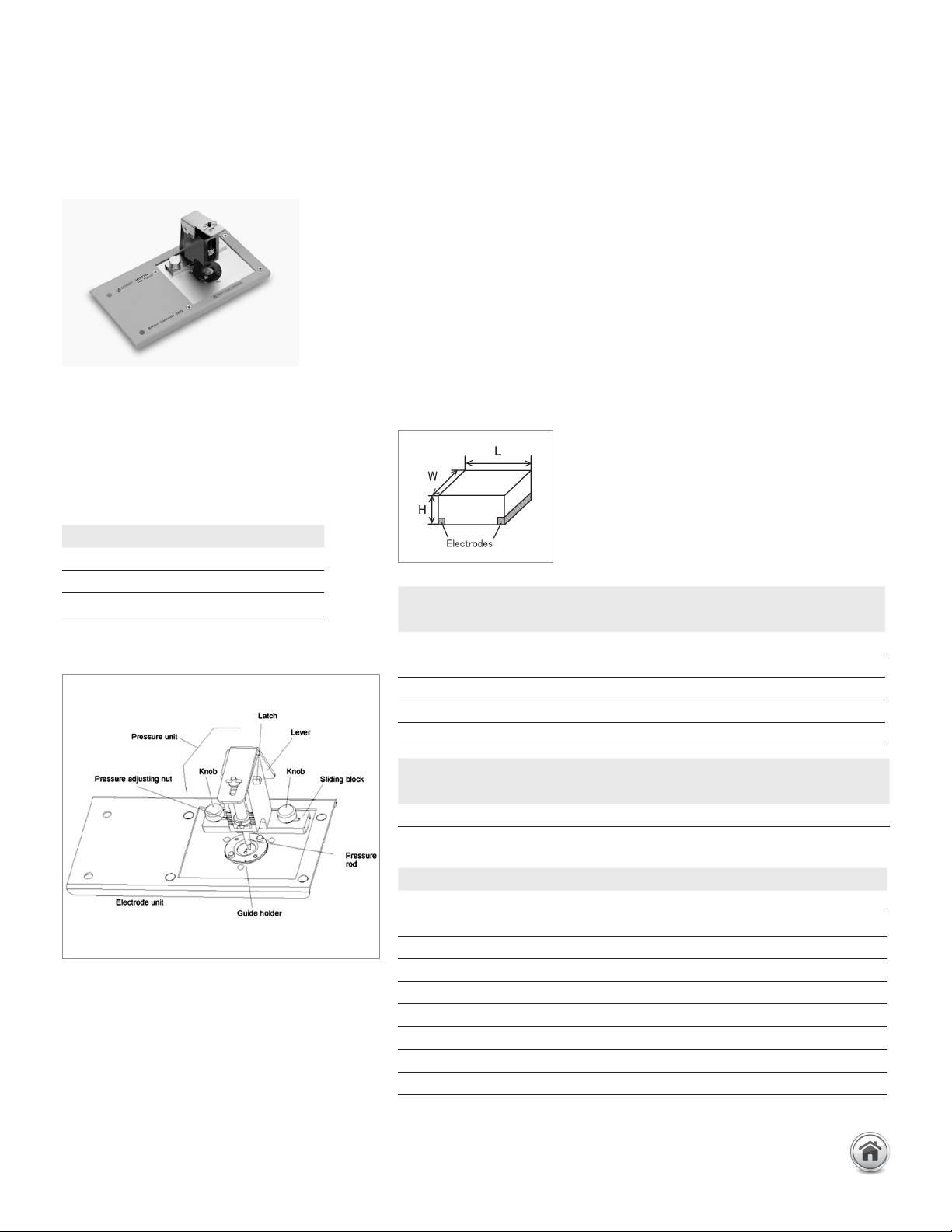
16197A Bottom electrode SMD
test fixture
Terminal connector: 7 mm
DUt connection: 2-Terminal
Electrical length: 14 mm
Dimensions (approx.):
160 (W) x 70 (H) x 86 (D) [mm]
Weight (approx.): 300 g
Additional error:
f: frequency [GHz]
Up to 3 GHz (7 mm): SMD continued
Description: This test fixture is designed for impedance evaluations of bottom
electrode SMDs. It achieves stable frequency characteristics up to 3 GHz and
provides highly repeatable measurements. This test fixture supports various SMD
sizes, as small as 1005 (mm)/0402 (inch) and as large as 3225 (mm)/1210 (inch).
Accommodation of the 0603 (mm)/0201 (inch) size is available with option 001.
Applicable instrument: E4982A, E4990A + 42942A*, E4991B, E5061B-3L3/
3L4/3L5 with Opt. 005 + 16201A
* Option E4990A-120 is required
Frequency: DC to 3 GHz
Maximum voltage: ±42 V peak max. (AC +DC)
Operating temperature: –55 to +85°C
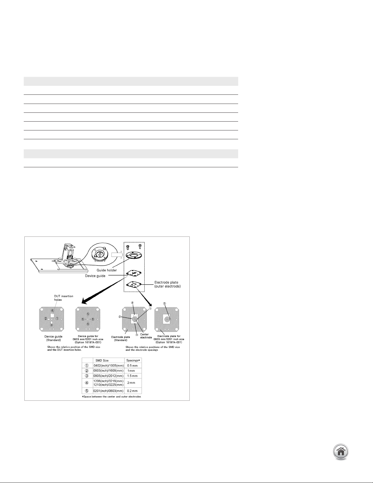
DUT size: See figure and table below:
Test fixture overview
Type of error Impedance
Proportional error 1.0 x f
2
[%]
Open repeatability 5 + 40 x f [
µ
S]
Short repeatability 30 + 125 x f [mΩ]
Description P/N Qty.
Operation and service manual 16197-90000 1
Device guide
1
16197-25005 2
Electrode plate
2
16197-00603 1
Cleaning rod 5182-7586 1
Blank device guide 16197-25006 3
Magnifying glass 16193-60002 1
Tweezers 8710-2081 1
Wrench 8710-0909 1
Carrying case
16197-60060
1
Standard option Applicable SMD size
SMD size code L x W [mm] H [mm]
3225 (mm)/1210 (inch) (3.2 ±0.15) x (2.5 ±0.15) H ≥ 0.4
3216 (mm)/1206 (inch) (3.2 ±0.15) x (1.6 ±0.15) H ≥ 0.4
2012 (mm)/0805 (inch) (2.0 ±0.15) x (1.25 ±0.15) H ≥ 0.4
1608 (mm)/0603 (inch) (1.6 ±0.15) x (0.8 ±0.15) H ≥ 0.4
1005 (mm)/0402 (inch) (1.0 ±0.1) x (0.5 ±0.1) H ≥ 0.4
Option 16197A-001 Applicable SMD size
SMD size code L x W [mm] H [mm]
0603 (mm)/0201 (inch) (0.6 ±0.03) x (0.3 ±0.03) H ≥ 0.25
1. One is delivered attached to the test fixture
2. Delivered attached to the fixture
Furnished accessories:
43 | Keysight | Accessories Catalog for Impedance Measurements - Catalog
Up to 3 GHz (7 mm): SMD continued
EIA/EIAJ Size shorting bar set (furnished)
16197A-001 Shorting bar
Options:
16197A-001: Add 0603 (mm)/0201 (inch) Device guide set
The 16197A’s electrode spaces are 0.5 mm, 1 mm, 1.5 mm and 2 mm and the device
guide matches these spaces with appropriate insertion holes for the applicable SMD.
The 0.2 mm electrode spacing is available with option 001, which includes a device
guide with 0603 mm/0201inch insertion holes, an electrode plate and 4 shorting
devices.
Compensation and measurement: First of all, select the appropriate device insertion
hole. If the device insertion hole is not positioned in the pressure arm’s contact range,
reposition the device guide and the electrode plate. Once this is prepared, perform
compensation. Open and short compensations are recommended in combination with
the electrical length compensation before measurement. The fixture’s electrical length
must be entered into the electrical length compensation function of the measurement
Electrodes configuration and SMD size
Size P/N Qty.
1 x 0.5 x 0.5 (mm) 16191-29005 1
1.6 x 0.8 x 0.8 (mm) 16191-29006 1
2.0 x 1.2 x 0.8 (mm) 16191-29007 1
3.2 x 1.6 x 0.8 (mm) 16191-29008 1
Device Guide 16197-25007 1
Electrode Plate 16197-00604 1
Size P/N Qty.
0.6 x 0.3 x 0.3 (mm) 16197-29001 4
16197A Bottom electrode SMD test fixture continued
44 | Keysight | Accessories Catalog for Impedance Measurements - Catalog