5965-4792.pdf - 第17页
1 6 33 4A T weeze rs contac t test f i x t ure T erminal connector : 4- T er minal P air , BNC DUT connec tion: 2 -Te r m i n a l Cable lengt h (approx. ): 1 m (fro m BNC connec tors to the top of tweezer s ) Wei gh t (a…
16034H Test fixture
Terminal connector: 4-Terminal Pair, BNC
DUT connection: 2-Terminal
Dimensions (approx.):
120 (W) x 50 (H) x 70 (D) [mm]
Weight (approx.): 200 g
Additional error:
f: [MHz]
Up to 120 MHz (4-Terminal Pair): SMD continued
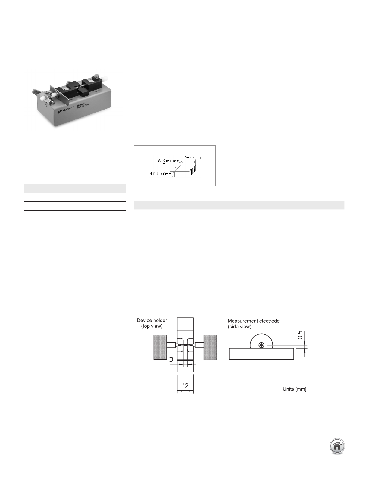
Description: This test fixture is designed for impedance evaluations of array-type SMD.
The minimum SMD size that this fixture is adapted to evaluate is 1.6(L) x 0.8(W) [mm].
Since the tip of the measurement electrodes are very thin and the device holder is
extremely flat, the device can be shifted and the measurement electrodes can contact
the each element of the array-type component.
Applicable instruments: E4980A/AL, E4981A, E4990A, E5061B-3L3/3L4/3L5
with Opt. 005
Frequency: DC to 120 MHz
Maximum voltage: ±42 V peak max. (AC+DC)
Operating temperature: 0 to 55°C
DUT size: See figure below
Furnished accessories:
Compensation and measurement: Open and short compensations are recommended
before measurement. When measuring above 3 MHz, load compensation is also
recommended. Open compensation is performed by separating the high and the low
electrodes from each other. The separation should be equivalent in size to the DUT’s
width. Short compensation is performed by placing the high and low electrodes in
contact together. Load compensation is performed by using the furnished 100 Ω SMD
chip resistor. After performing open, short and load compensations, the DUT is inserted
into the test fixture. Refer to the 16034G figures to see how compensation and meas-
urement are performed.
Electrode dimensions
Description P/N Qty.
Case for 100 Ω SMD resistance 1540-0692 1
100 Ω chip resistor 0699-2488 10
Operating manual 16034-90012 1
Type of error Impedance
Proportional error 0.5 x (f/10)
2
[%]
Open repeatability 5 + 500 x (f/10) [nS]
Short repeatablity 10 + 13 x (f/10) [mΩ]
13 | Keysight | Accessories Catalog for Impedance Measurements - Catalog
16334A Tweezers contact test
fixture
Terminal connector: 4-Terminal Pair, BNC
DUT connection: 2-Terminal
Cable length (approx.): 1 m (from BNC
connectors to the top of tweezers)
Weight (approx.): 290 g
Additional error:
f: [MHz]
Up to 120 MHz (4-Terminal Pair): SMD continued
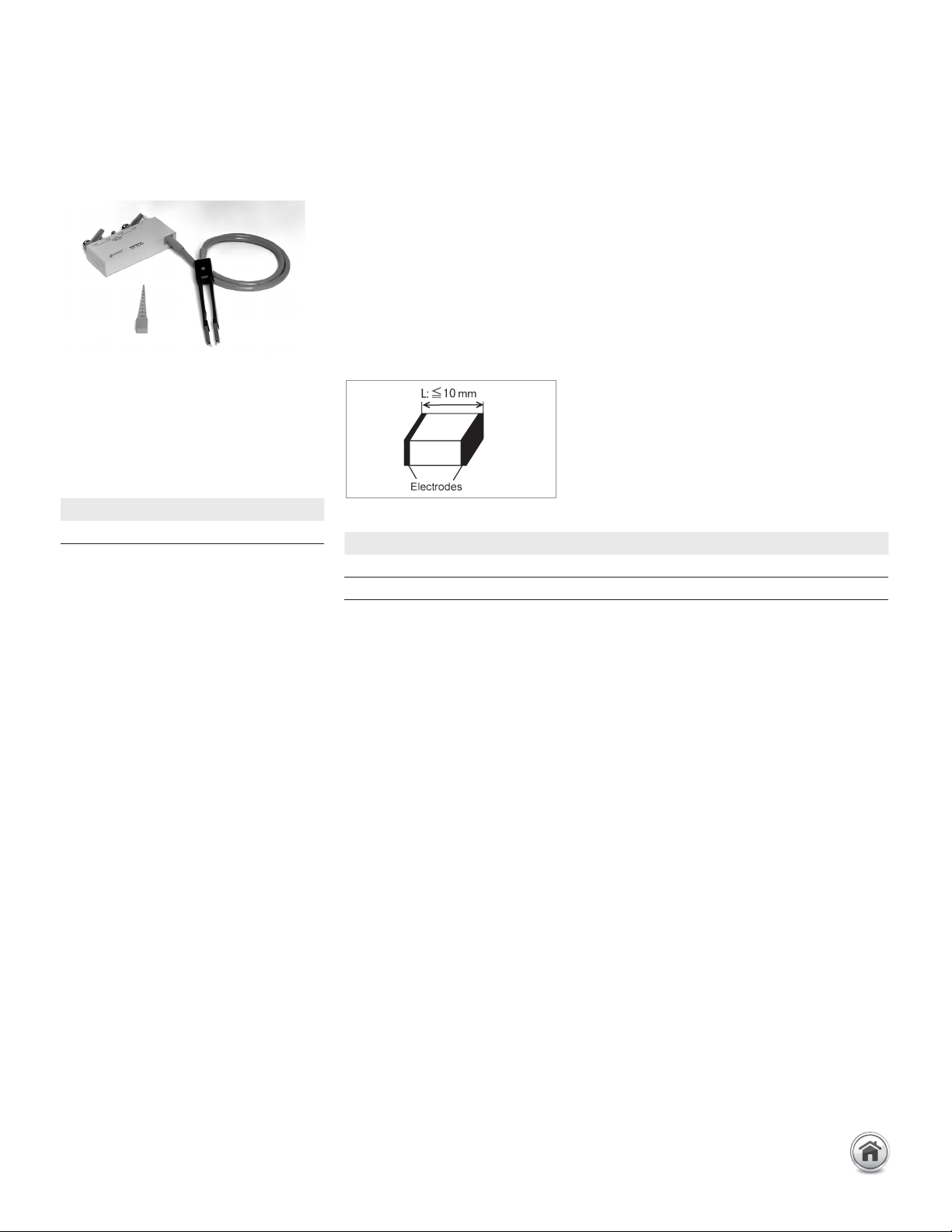
Description: This test fixture is designed for impedance evaluations of SMD. The
minimum SMD size that this fixture is adapted to evaluate is 1.6(L) x 0.8(W) [mm]. The
tweezers’ contacts on this fixture makes it easy to hold the DUT.
Applicable instruments: E4980A/AL, E4981A, E4990A
Frequency: 5 Hz to 15 MHz
Maximum voltage: ±42 V peak max. (AC+DC)
Operating temperature: 0 to 55°C
DUT size: ≤10 mm (width)
See figure below
Furnished accessories:
Compensation and measurement: Open and short compensations are recommended
before measurement. Open and short compensations are performed by using the
furnished compensation block. After performing open and short compensations, the
DUT is sandwiched by the tweezers’ contacts and is measured.
Description P/N Qty.
Compensation block 16334-60001 1
Operating note 16334-90000 1
Type of error Impedance
Proportional error ±2 x (f/10)
2
14 | Keysight | Accessories Catalog for Impedance Measurements - Catalog
Up to 120 MHz (4-Terminal Pair): Other Components
16089A Large Kelvin clip leads
Terminal connector:
4-Terminal Pair, BNC
DUT connection: 4-Terminal
Cable length (approx.):
0.94 m (from connector to clip's tip)
Weight (approx.): 300 g
Additional error: The additional error is
negligible when compared to the instru-
ment's accuracy.
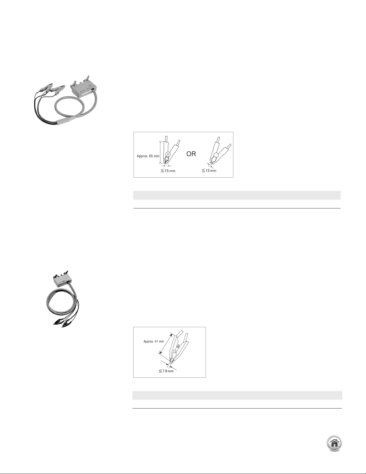
Description: This test fixture makes it possible to measure odd-shaped components
that cannot be measured with conventional fixtures. It is equipped with two insulated
Kelvin clips.
Applicable instruments: E4980A/AL, E4981A, E4990A
Frequency: 5 Hz to 100 kHz
Maximum voltage: ±42 V peak max. (AC+DC)
Operating temperature: 0 to 55°C
DUT size:
See figure below
Furnished accessories:
Compensation and measurement: Open and short compensations are recommended
before measurement. For open compensation, do not connect the Kelvin clips to any-
thing. Short compensation is performed by holding a shorting plate with the Kelvin clips.
After performing open and short compensations, the DUT is held with the Kelvin clips.
16089B Medium Kelvin clip leads
Terminal connector: 4-Terminal Pair, BNC
DUT connection: 4-Terminal
Cable length (approx.):
0.94 m (from connector to clip's tip)
Weight (approx.): 300 g
Additional error: The additional error is neg-
ligible when compared to the instrument's
accuracy.
Description: This test fixture makes it possible to measure odd-shaped components
that cannot be measured with conventional fixtures. It is equipped with two insulated
Kelvin clips.
Applicable instruments: E4980A/AL, E4981A, E4990A
Frequency: 5 Hz to 100 kHz
Maximum voltage: ±42 V peak max. (AC+DC)
Operating temperature: 0 to 55°C
DUT size: See figure below
Furnished accessories:
Compensation and measurement: Open and short compensations are recommended
before measurement. For open compensation, do not connect the Kelvin clips to anything.
Short compensation is performed by connecting the Kelvin clips together. After
performing open and short compensations, the DUT is held with the Kelvin clips.
Description P/N Qty.
Operating and service manual 16089-90020 1
Description P/N Qty.
Operating and service manual 16089-90020 1
15 | Keysight | Accessories Catalog for Impedance Measurements - Catalog