5965-4792.pdf - 第26页
1 6 451 B D ielectric test f ix ture continued Applica ble instr uments: E49 8 0A / A L , E49 81A, E4 9 9 0A Frequ ency: D C to 30 MH z Ma ximum v oltag e: ±42 V peak ma x . (A C+DC) Operating te mperature: 0 to 55° C Ma…
16451B Dielectric test fixture
Terminal connector: 4-Terminal pair, BNC
Dimension (approx.): See page 26
Cable length (approx.):
0.8 m(from connector to electrodes)
Weight (approx.): 3700 g
Measurement accuracy
(supplemental performance characteristics):
f: measured frequency [Hz] f ≤ 30 MHz
ε�
rm
: measured permittivity
tan δ: measured dissipation factor
ε
0
: permittivity of air 8.854 × 10
-12
[F/m]
d: diameter of electrode {A,B}
t: thickness of material [mm]
Az: Impedance measurement error of instrument
Ad: D measurement error of instrument
The material is assumed to be ideally flat.
The above equation is applicable for electrodes A
and B when using the contacting electrode method.
Up to 120 MHz (4-Terminal Pair): Material
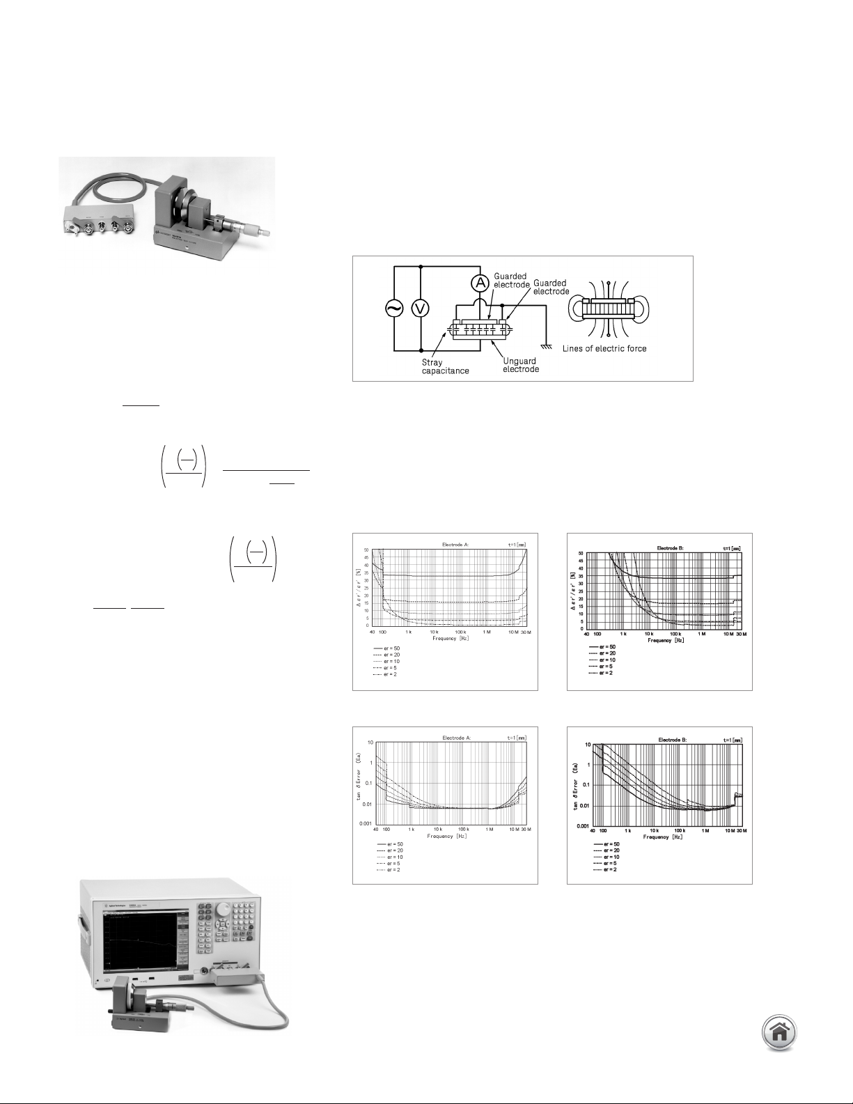
Description: The 16451B is used to evaluate the dielectric constant of solid
dielectric materials accurately, and complies with ASTM D150. The 16451B
employs the parallel plate method, which sandwiches the material between two
electrodes to form a capacitor. LCR meter or an Impedance Analyzer is then
used to measure the capacitance created from the fixture. A measurement block
diagram of the parallel plate method is shown below:
Notice the stray capacitance, which is formed on the test material as shown in
the figure above. The guard electrode helps to eliminate the stray capacitance
at the edge of the electrode.
Basic measurement accuracy (including the E4990A):
Parallel plate method
Typical Permittivity (εr�) Measurement Accuracy:
E4990A with 16451B
Typical Loss Tangent (tan δ) Measurement Accuracy:
ε
'
r
accuracy ()
ε
'
rm
∆
ε
'
rm
A
Z +
0.04 f
2
ε
'
rm
ε
0 +
2
d
t
2
100 (
ε
'
rm
–
1)
(
ε
'
rm
–
)
t
0.01
[%]
π
2
d
t
2
Ea = 0.005 + 0.0004 f
2
ε
'
rm
ε
0
π
E
b
=
100
tan δ
ε
'
rm
∆
ε
'
rm
tan δ < 0.1:
ε* Loss Tangent Accuracy (∆ tan δ)
tan δ < 0.1 : Ad + Ea + Eb
E4990A Measurement settings;
1. Osc level : 500 mV
2. Meas Time: 5 Precise
3. Adapter setup : 1 m
4. Compensation : Open, short and load
22 | Keysight | Accessories Catalog for Impedance Measurements - Catalog
16451B Dielectric test fixture continued
Applicable instruments: E4980A/AL, E4981A, E4990A
Frequency: DC to 30 MHz
Maximum voltage: ±42 V peak max. (AC+DC)
Operating temperature: 0 to 55°C
Material size:
Up to 120 MHz (4-Terminal Pair): Material continued
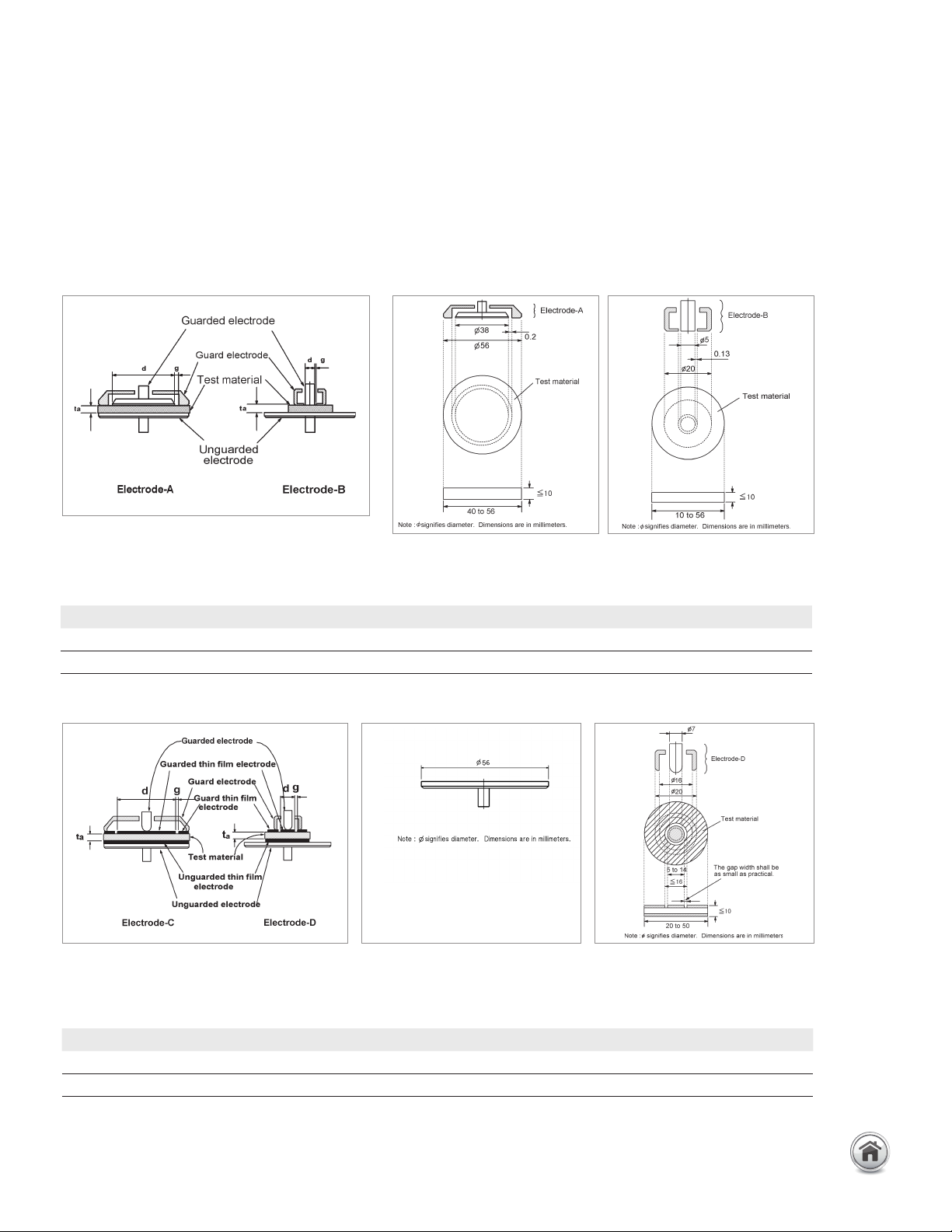
Electrodes for contacting electrode method (Rigid Metal
Electrode)
Material size for electrode-A Material size for electrode-B
Electrodes for contacting electrode method (Thin Film
Electrode)
Material size for electrode-C Material size for electrode-D
Equipped with Electrodes A and B for flat and smooth materials.
Equipped with Electrodes C and D for rough or extremely thin materials.
* diameter of applied thin film electrode
Electrode type Diameter of MUT Thickness of MUT Diameter of electrode Max. frequency
A 40 mm ~ 56 mm t ≤ 10 mm 38 mm 30 MHz
B 10 mm ~ 56 mm t ≤ 10 mm 5 mm 30 MHz
Electrode type Diameter of MUT Thickness of MUT Diameter of electrode Max. frequency
C 56 mm t ≤ 10 mm 5 ~ 50 mm 30 MHz
D 20 mm ~ 56 mm t ≤ 10 mm 5 ~ 14 mm 30 MHz
23 | Keysight | Accessories Catalog for Impedance Measurements - Catalog
16451B Dielectric test fixture continued
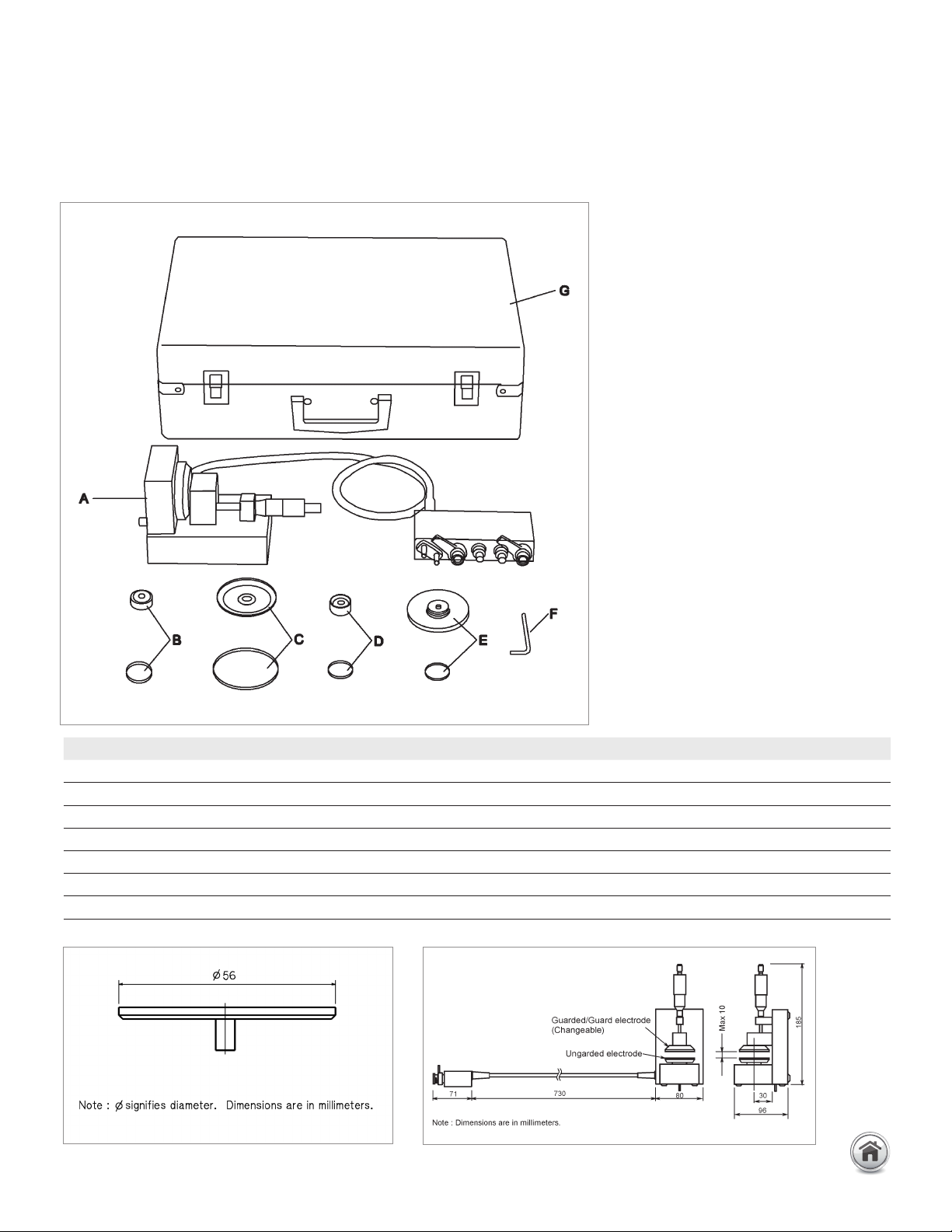
Furnished accessories:
Up to 120 MHz (4-Terminal Pair): Material continued
Dimensions of unguarded electrode
Dimensions of fixture assembly
Description P/N Qty.
Test Fixture including Electrode-A, unguarded electrode and cover N/A 1 A
Electrode-B and cover 16451-60013 1 B
Electrode-C and cover 16451-60012 1 C
Electrode-D and cover 16451-60014 1 D
Attachment for error compensation and cover 16451-60021 1 E
Hex key (for replacing electrodes) 5188-4452 1 F
Carrying Case 16451-60001 1 G
24 | Keysight | Accessories Catalog for Impedance Measurements - Catalog