5965-4792.pdf - 第30页
U p to 1 20 MHz ( 4- T ermi nal Pai r ): Ma teri al c onti nued Compens ation and measur ement: Shor t compensation is recommended in comb ination wi th th e cab le lengt h comp ensa tion be fore m easur ement . Fir st ,…
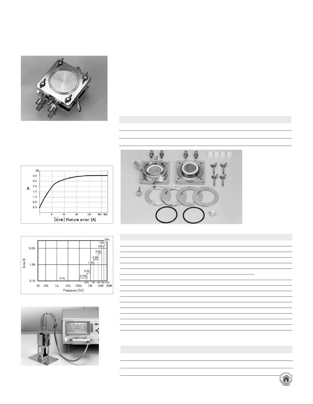
16452A Liquid dielectric test fixture
Terminal connector: 4-Terminal Pair, SMA
Dimensions (approx.): 8
5 (H) x 85 (W) x 37 (D) [mm]
Weight (approx.): 1400 g
Measurement accuracy: A + B + C [%]
Up to 120 MHz (4-Terminal Pair): Material continued
Description: This test fixture provides accurate dielectric constant and impedance
measurements of liquid materials. The 16452A employs the parallel plate method,
which sandwiches the liquid material between two electrodes to form a capacitor.
A LCR meter or an impedance analyzer is then used to measure the capacitance
created from the fixture.
Applicable instruments: E4980A/AL, E4990A
Frequency: 20 Hz to 30 MHz
Operating temperature: –20 to 125°C
Maximum voltage: 30 Vrms
Material capacity: Required sample liquid capacity depends on the gap of the electrodes.
Furnished accessories:
Requires the following interface cables to connect to a measurement instrument. Select
accordingly to the required temperature conditions.
* Four BNC(m) to BNC(m) adapters (P/N 1250-0216) are needed to connect
the 16048G/H and 16452A.
Error B [%]
Error A [%]
Error C [%] = Measurement Error of Instrument
LCR meter with 16452A
(A)
(H)
(B)
(I)
(C)
(F)
(E)
(D)
(G)
Gap of electrodes 0.3 mm 0.5 mm 1 mm 2 mm
Air capacitance 34.9 pF ±25% 21.2 pF ±15% 10.9 pF ±10% 5.5 pF ±10%
Sample liquid capacity 3.4 ml 3.8 ml 4.8 ml 6.8 ml
Applicable frequency 20 Hz – 30 MHz
Temperature Model# or P/N Cable length (approx.)
0 to 55°C 16048A 0.94 m
–20 to 150°C 16048G* for E4990A only 1 m
–20 to 150°C 16048H* for E4990A only 2 m
Description P/N Qty.
Shorting plate 16092-08010 1 E
O-ring for liquid outlet 0905-1277 1 D
Spacer (1.3 mm thickness) 16452-00601 1 F
Spacer (1.5 mm thickness) 16452-00602 1 F
Spacer (2.0 mm thickness) 16452-00603 1 F
Spacer (3.0 mm thickness) 16452-00604 1 F
Lid of liquid outlet 16452-24002 1 G
SMA-BNC adapter 1250-1200 4 H
Waterproof cap for BNC connector 1252-5821 4 I
Carrying case 16452-60111 1 –
Operation and service manual 16452-90020 1 –
Angle iron of stand body for fixture stand 16452-01201 2 –
Screw of stand body or fixture stand 0515-0914 4 C
Screw for fixture stand 0515-0914 4 –
Stand foot
16452-00611
1 –
Electrode (high and low) NA 2 A.B
26 | Keysight | Accessories Catalog for Impedance Measurements - Catalog
Up to 120 MHz (4-Terminal Pair): Material continued
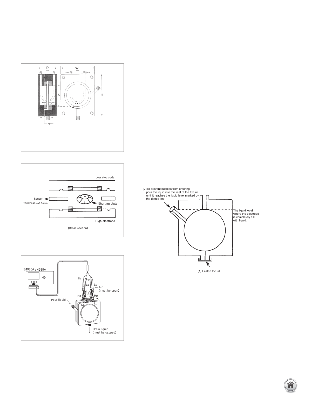
Compensation and measurement: Short compensation is recommended
in combination with the cable length compensation before measurement.
First, set the instrument’s cable length compensation function to 1 m. Then,
short compensation is performed by using the furnished shorting plate. Open
compensation is not performed, but its values are used in the dielectric constant
equation as shown below:
Cp 1
ε
r
= α (
__
– j
_______
)
Co ω CoRp
α : Correction coefficient
ε
r
: Relative dielectric constant
Cp : Liquid capacitance (measurement data)
Co : Air capacitance (measurement data) or open compensation data
Rp : Equivalent parallel resistance (measurement data)
ω : Angular frequency (ω= 2πf)
The following figures below show how compensation and measurement is
performed.
Note: The 16452A is not capable of measuring salt or ionic solutions or other
liquids with bulk conductivity due to the electrode polarization phenomenon.
Keysight is not responsible for any damage (e.g., corrosion, smear) to the 16452A
caused by the reaction between the liquid under test and the 16452A.
Test fixture overview
Short compensation
Method of connection
Pouring the liquid into the fixture
Fixture materials
Electrode: Ni plated Cobal
(Fe 54%, Co 17%, Ni 29%)
Insulator: Alumina (Al
2
O
3
)
O-ring: Viton (Fluro rubber)
16452A Liquid dielectric test fixture continued
27 | Keysight | Accessories Catalog for Impedance Measurements - Catalog
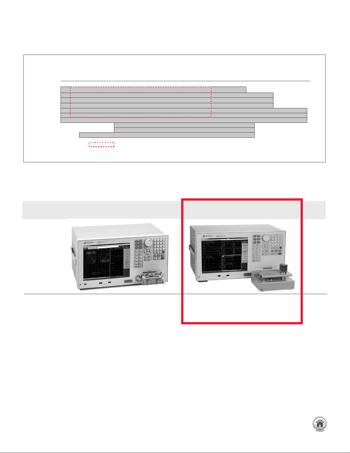
Frequency Up to 120 MHz Up to 3 GHz
range (Terminal configuration: 4-Terminal Pair) (Terminal configuration: 7 mm)
Measurement E4980A/AL, E4981A, E4990A E4982A, E4990A + 42942A*, E4991B,
instruments
E5061B-3L3/3L4/3L5 w/Opt. 005 + 16201A
* Option E4990A-120 is required
Up to 3 GHz (7 mm)
Frequency range
DC 1 k 1 M 10 M 100 M 1 G [Hz] 2 G [Hz] 3G [Hz]
16092A
500 M
16192A 2 G
16193A 2 G
16194A 2 G
16196A/B/C/D 3 G
16197A
16198A
3 G
3 G
16200B
1 M
1 G
16453A
1 M
1 G
16454A 1k
1 G
: When 42942A is used.
Applicable instrument
28 | Keysight | Accessories Catalog for Impedance Measurements - Catalog