5965-4792.pdf - 第24页
U p to 1 20 MHz ( 4- T ermi nal Pai r ): DC Bi as A cces sori e s 1 6 0 65C 40 Vd c ex ternal volt age bia s adap ter T erminal connector : 4- T er minal P air , BNC E x tern al bias i nput co nnec tor : BNC (f ) Dimensi…
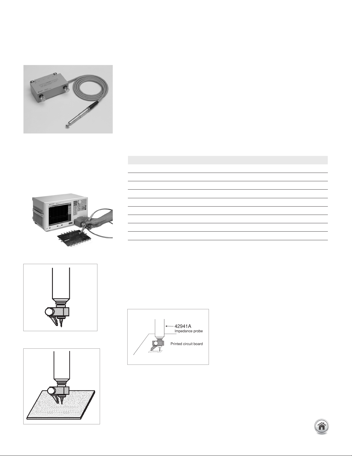
42941A Impedance probe kit
Terminal connector: 4-Terminal pair, BNC
Cable length (approx.): 1.5 m
Weight (approx.): 2400 g
Basic measurement accuracy: ±1%
For detailed information, refer to the
operation manual or the specifications of
E4990A-120.
Up to 120 MHz (4-Terminal Pair): Probes
Description: This impedance probe kit is designed for use with the E4990A-120. It
provides the capability to perform in-circuit measurements (printed circuit patterns,
the input/output impedance of circuits, etc.) with better accuracy and wider impedance
coverage from 20 Hz to 120 MHz. DUTs can be connected by either using the pin probe,
the clip lead (alligator clip adapter) or the BNC adapter. All probe adapter can be used
from 20 Hz to 120 MHz. The pin probe is best for in-circuit, board-mounted compo-
nents, The clip lead is for components too large for the pin probe. The BNC adapter is
used to connect circuits or networks equipped with BNC connectors.
Applicable instrument: E4990A-120
Frequency: 20 Hz to 120 MHz
Maximum voltage: ±42 V peak max. (AC+DC)
Operating temperature: –20 to +75°C (probe only)
Furnished accessories:
Compensation and measurement: Adapter setup and compensation is required before
measurement. In the Adapter setup menu, select PROBE 42941A. Use the furnished
3.5 mm short and load standards. The open condition can be created by not connecting
the probe to anything. Perform phase compensation, short and load data measure-
ments. For compensation, open and short compensation is recommended. Short
compensation is performed by shorting the probe. To short the probe it is recommended
to use a shorting device with gold-plated surfacing (which provides stable contact
resistance).
E4990A-120 with 42941A
In-circuit measurement
Open compensation
Short compensation
Description P/N Qty.
Pin probe 42941-60002 1
Adapter BNC-SMA
1250-2375 1
Spare pin Set (3 ea.) 42941-60004 1
3.5 mm SHORT 1250-2840 1
3.5 mm LOAD 0955-1105 1
Clip lead 8121-0003 1
Ground lead 04193-61679 1
Carrying case 42941-60011 1
Operating and service manual 42941-90010 1
20 | Keysight | Accessories Catalog for Impedance Measurements - Catalog
Up to 120 MHz (4-Terminal Pair): DC Bias Accessories
16065C 40 Vdc external
voltage bias adapter
Terminal connector: 4-Terminal Pair, BNC
External bias input connector: BNC(f)
Dimensions (
approx.): 160 (W) x 50 (H) x 150 (D) [mm]
Cable length (approx.): 210 mm
Weight (approx.): 450 g
LCR meter with 16065C
Description: This test fixture makes it possible to measure a DUT with up to ±200
V DC bias. The same modules of 16047A can be used to allow measurements of
axial/radial lead components.
Applicable instruments: E4980A/AL, E4981A, E4990A
Frequency: 50 Hz to 2 MHz
Maximum DC bias: ±200 V DC max. /15 V peak AC max.
Blocking capacitor of 5.6 µF is connected in with the Hc terminal.
Operating temperature: 0 to 55°C
DUT Size: See the 16047A figure with module sizes.
Furnished accessories:
Compensation and measurement: Open, short and load compensations are recom-
mended before measurement. Short compensation is performed by shorting the
contacts of the test fixture with a shorting plate as described for the 16047A. Load
compensation is performed by inserting a known standard device. After performing
open, short and load compensations, the DUT is connected to the test fixture.
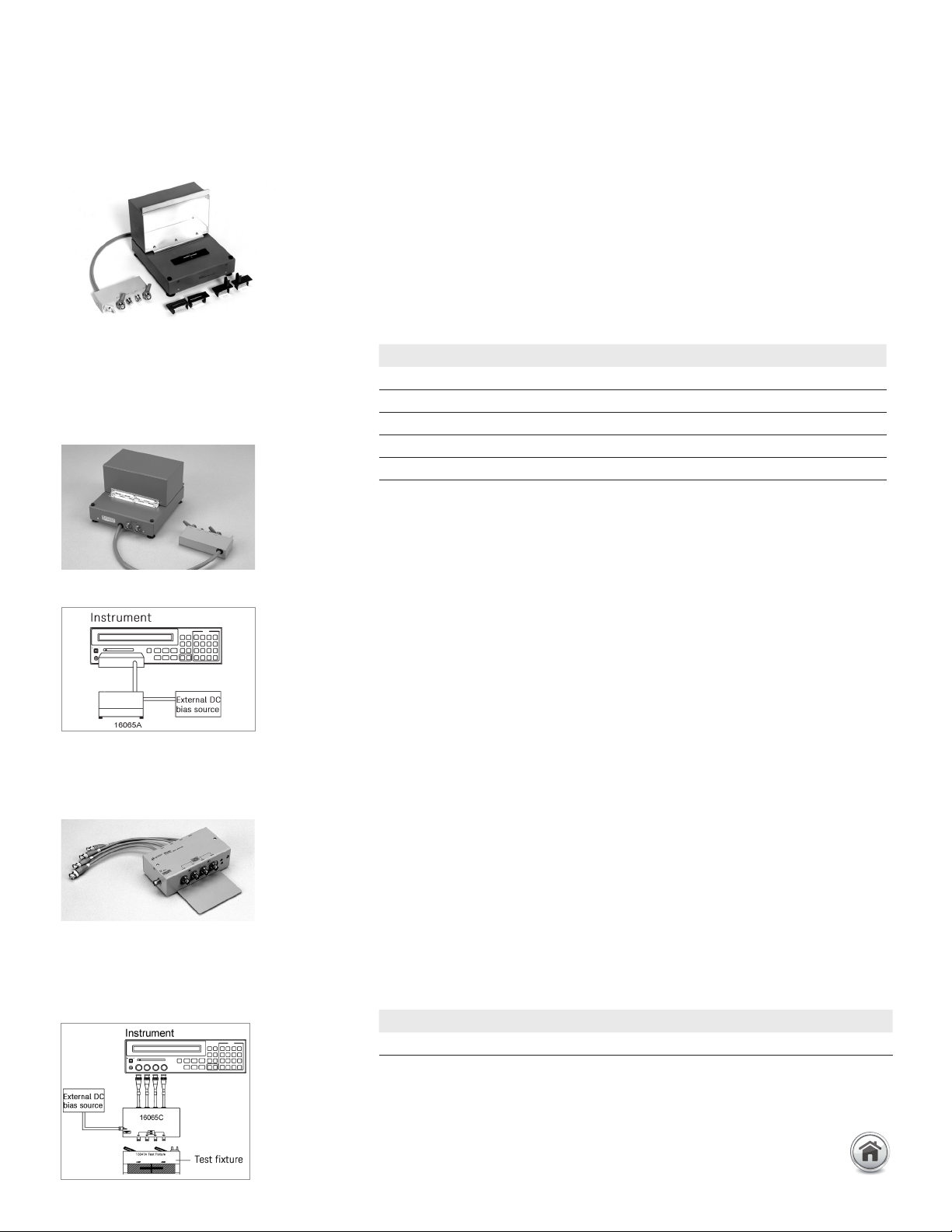
Description: This adapter is designed to operate specifically with the E4981A
and the E4980AL. By connecting an external DC voltage source to this adapter, a
bias voltage of up to ±40 V can be supplied to a DUT. The DUT can be inserted by
connecting any direct attachment 4-Terminal Pair test fixture to the adapter.
Applicable instruments: E4981A and E4980AL
Frequency: 100 Hz to 1 MHz
Maximum DC bias: ±42 V peak max. (AC+DC)
Blocking Capacitor of 100 µF is connected in series with the Hc terminal.
Operating temperature: 0 to 55°C
Applicable fixtures: 16034E/G/H, 16047A/E, 16048A/D, 16089A/B/C
Furnished accessories:
Compensation and measurement: Open and short compensations are recom-
mended before measurement. Short compensation is performed by shorting
the contacts of the test fixture that is in use. After performing open and short
compensations, the DUT is connected to the test fixture.
Description P/N Qty.
Module for axial lead 16061-70022 1
Module for radial lead mounting on fixture 16061-70021 1
Module for short radial lead 16047-65001 1
Shorting bar 16047-00640 1
Operating and service manual 16065-90011 1
Description P/N Qty.
Operating and service manual 16065-90020 1
16065A 200 Vdc external voltage
bias fixture
Terminal connector: 4-Terminal Pair, BNC
DUT connection: 4-Terminal
External bias input connector: High Voltage BNC(f)
Dimensions
(approx.): 180 (W) x 120 (H) x 200 (D) [mm]
Cable length (approx.): 40 cm
Weight (approx.): 1500 g
High Voltage BNC(f) connector for external bias input
BNC(f) connector for voltage monitor output
LCR meter with 16065A
21 | Keysight | Accessories Catalog for Impedance Measurements - Catalog
16451B Dielectric test fixture
Terminal connector: 4-Terminal pair, BNC
Dimension (approx.): See page 26
Cable length (approx.):
0.8 m(from connector to electrodes)
Weight (approx.): 3700 g
Measurement accuracy
(supplemental performance characteristics):
f: measured frequency [Hz] f ≤ 30 MHz
ε�
rm
: measured permittivity
tan δ: measured dissipation factor
ε
0
: permittivity of air 8.854 × 10
-12
[F/m]
d: diameter of electrode {A,B}
t: thickness of material [mm]
Az: Impedance measurement error of instrument
Ad: D measurement error of instrument
The material is assumed to be ideally flat.
The above equation is applicable for electrodes A
and B when using the contacting electrode method.
Up to 120 MHz (4-Terminal Pair): Material
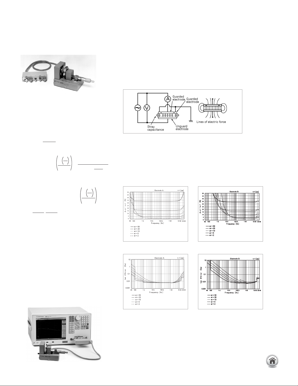
Description: The 16451B is used to evaluate the dielectric constant of solid
dielectric materials accurately, and complies with ASTM D150. The 16451B
employs the parallel plate method, which sandwiches the material between two
electrodes to form a capacitor. LCR meter or an Impedance Analyzer is then
used to measure the capacitance created from the fixture. A measurement block
diagram of the parallel plate method is shown below:
Notice the stray capacitance, which is formed on the test material as shown in
the figure above. The guard electrode helps to eliminate the stray capacitance
at the edge of the electrode.
Basic measurement accuracy (including the E4990A):
Parallel plate method
Typical Permittivity (εr�) Measurement Accuracy:
E4990A with 16451B
Typical Loss Tangent (tan δ) Measurement Accuracy:
ε
'
r
accuracy ()
ε
'
rm
∆
ε
'
rm
A
Z +
0.04 f
2
ε
'
rm
ε
0 +
2
d
t
2
100 (
ε
'
rm
–
1)
(
ε
'
rm
–
)
t
0.01
[%]
π
2
d
t
2
Ea = 0.005 + 0.0004 f
2
ε
'
rm
ε
0
π
E
b
=
100
tan δ
ε
'
rm
∆
ε
'
rm
tan δ < 0.1:
ε* Loss Tangent Accuracy (∆ tan δ)
tan δ < 0.1 : Ad + Ea + Eb
E4990A Measurement settings;
1. Osc level : 500 mV
2. Meas Time: 5 Precise
3. Adapter setup : 1 m
4. Compensation : Open, short and load
22 | Keysight | Accessories Catalog for Impedance Measurements - Catalog