5965-4792.pdf - 第28页
1 6 451 B D ielectric test f ix ture continued Compens ation and measur ement: Ther e are t hree mea surem ent met hods f or the 1 6 4 5 1 B. T hey ar e the Co ntac ting El ect rode M etho d ( us ed wi th 1 6 4 5 1 B ’ s…
16451B Dielectric test fixture continued
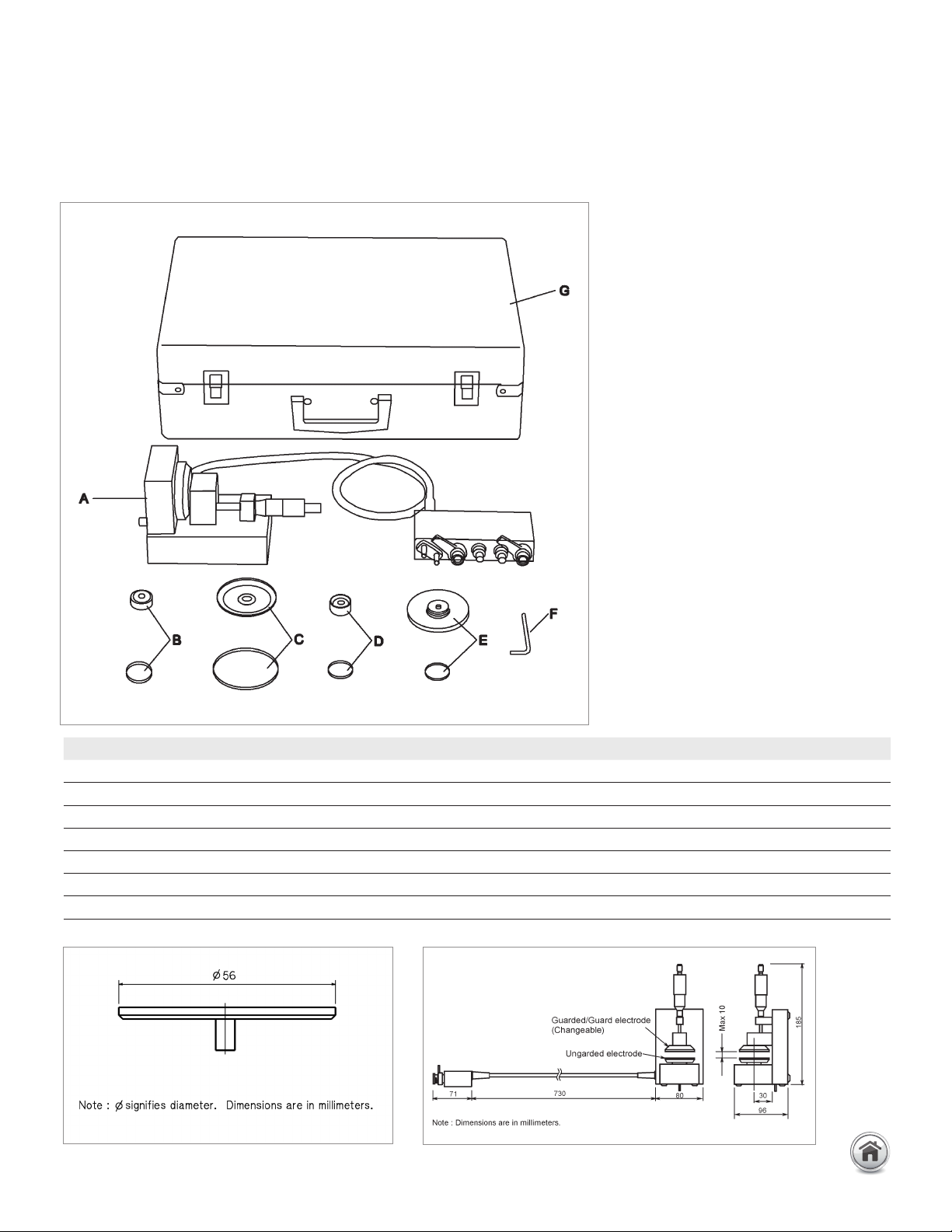
Furnished accessories:
Up to 120 MHz (4-Terminal Pair): Material continued
Dimensions of unguarded electrode
Dimensions of fixture assembly
Description P/N Qty.
Test Fixture including Electrode-A, unguarded electrode and cover N/A 1 A
Electrode-B and cover 16451-60013 1 B
Electrode-C and cover 16451-60012 1 C
Electrode-D and cover 16451-60014 1 D
Attachment for error compensation and cover 16451-60021 1 E
Hex key (for replacing electrodes) 5188-4452 1 F
Carrying Case 16451-60001 1 G
24 | Keysight | Accessories Catalog for Impedance Measurements - Catalog

16451B Dielectric test fixture continued
Compensation and measurement: There are three measurement methods for the
16451B. They are the Contacting Electrode Method (used with 16451B’s rigid metal
electrode, without any electrodes on the material under test), the Contacting Electrode
Method (used with thin film electrodes made on the material under test), and the Non-
Contacting Electrode (Air Gap method). Select the suitable measurement method and
the suitable electrode for the material under test according to the following table.
Summary of measurement method
Open and short compensations are recommended in combination with the cable length
compensation before measurement. When measuring above 5 MHz with the E4990A,
load compensation is also recommended. First, set the instrument’s cable length
compensation function to 1 m. Then, open and short compensation is performed by
using the furnished electrode attachment. Load compensation is performed, by prepar-
ing a working standard. After performing open, short and load compensations, the MUT
is sandwiched by the parallel electrodes and the capacitance is measured. Relative
permittivity is calculated from the measured capacitance in the following manner:
t
a
× C
p
εr�=
d
π × (—)
2
× ε
o
2
εr� : Relative permittivity
C
p
: Capacitance (measurement data)
o
: 8.854 × 10
–12
[F/m]
t
a
: Average thickness of test material
d : Diameter of guarded electrode
Up to 120 MHz (4-Terminal Pair): Material continued
Measurement
method
Contacting electrode method (used with
rigid metal electrode)
Contacting electrode method (used
with thin film electrode)
Non-contacting electrode method
Accuracy Low > High
Operation Simple > Complex
Applicable
materials
Thick, solid and smooth materials Materials on which thin film can
be applied without changing its
characteristics
Thick, and soft materials Rough
materials also
25 | Keysight | Accessories Catalog for Impedance Measurements - Catalog
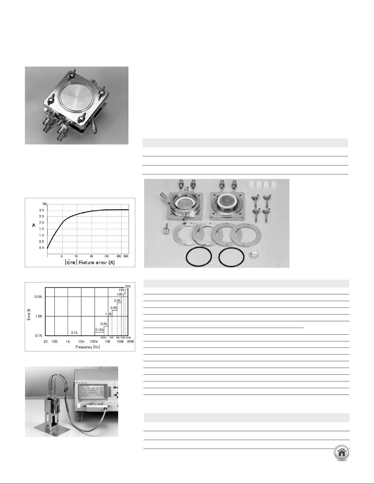
16452A Liquid dielectric test fixture
Terminal connector: 4-Terminal Pair, SMA
Dimensions (approx.): 8
5 (H) x 85 (W) x 37 (D) [mm]
Weight (approx.): 1400 g
Measurement accuracy: A + B + C [%]
Up to 120 MHz (4-Terminal Pair): Material continued
Description: This test fixture provides accurate dielectric constant and impedance
measurements of liquid materials. The 16452A employs the parallel plate method,
which sandwiches the liquid material between two electrodes to form a capacitor.
A LCR meter or an impedance analyzer is then used to measure the capacitance
created from the fixture.
Applicable instruments: E4980A/AL, E4990A
Frequency: 20 Hz to 30 MHz
Operating temperature: –20 to 125°C
Maximum voltage: 30 Vrms
Material capacity: Required sample liquid capacity depends on the gap of the electrodes.
Furnished accessories:
Requires the following interface cables to connect to a measurement instrument. Select
accordingly to the required temperature conditions.
* Four BNC(m) to BNC(m) adapters (P/N 1250-0216) are needed to connect
the 16048G/H and 16452A.
Error B [%]
Error A [%]
Error C [%] = Measurement Error of Instrument
LCR meter with 16452A
(A)
(H)
(B)
(I)
(C)
(F)
(E)
(D)
(G)
Gap of electrodes 0.3 mm 0.5 mm 1 mm 2 mm
Air capacitance 34.9 pF ±25% 21.2 pF ±15% 10.9 pF ±10% 5.5 pF ±10%
Sample liquid capacity 3.4 ml 3.8 ml 4.8 ml 6.8 ml
Applicable frequency 20 Hz – 30 MHz
Temperature Model# or P/N Cable length (approx.)
0 to 55°C 16048A 0.94 m
–20 to 150°C 16048G* for E4990A only 1 m
–20 to 150°C 16048H* for E4990A only 2 m
Description P/N Qty.
Shorting plate 16092-08010 1 E
O-ring for liquid outlet 0905-1277 1 D
Spacer (1.3 mm thickness) 16452-00601 1 F
Spacer (1.5 mm thickness) 16452-00602 1 F
Spacer (2.0 mm thickness) 16452-00603 1 F
Spacer (3.0 mm thickness) 16452-00604 1 F
Lid of liquid outlet 16452-24002 1 G
SMA-BNC adapter 1250-1200 4 H
Waterproof cap for BNC connector 1252-5821 4 I
Carrying case 16452-60111 1 –
Operation and service manual 16452-90020 1 –
Angle iron of stand body for fixture stand 16452-01201 2 –
Screw of stand body or fixture stand 0515-0914 4 C
Screw for fixture stand 0515-0914 4 –
Stand foot
16452-00611
1 –
Electrode (high and low) NA 2 A.B
26 | Keysight | Accessories Catalog for Impedance Measurements - Catalog