5965-4792.pdf - 第53页
1 6 45 4A mag netic mat eria l test f i x t ure T erminal connector : 7 mm Dimensions ( appr o x.): (L arge t es t fi x ture) 30 (D ) x 3 5(H) [mm ] (Small te st f ix tur e ) 24(D) x 30 (H) [ mm] Wei gh t (ap pr ox .): (…
16453A Delectric material test
fixture
Terminal connector: 7 mm
Dimensions (approx.):
130 (H) x 50 (W) x 60 (D) [mm]
Weight (approx.): 600 g
Measurement accuracy (including the E4991B):
Up to 3 GHz (7 mm): Material
Description: The 16453A is designed for accurate dielectric constant and loss
tangent measurements on the E4991B. It employs the parallel plate method,
which sandwiches the material between two electrodes to form a capacitor.
E4991B measures the capacitance created from the fixture, and option
E4991B-002 firmware calculates the relative complex permittivity. Adjustment to
insure parallel electrodes is required when using the 16451B. This adjustment is
not required with 16453A because the fixture has a flexible electrode that adjusts
automatically to the material surface.
Applicable instruments: E4991B with Opt. E4991B-002
Frequency: 1 MHz to 1 GHz
Maximum voltage: ±42 V peak max. (AC+DC)
Operating temperature: –55 to 200°C
When Option E4991B-007 temperature characteristic test kit is used with
E4991B, the operating temperature range is between –55°C and +150°C.
Material size:
Furnished accessories:
Compensation and measurement: Open, short and load compensations are
recommended before measurement. Open compensation is performed by
separating the high and the low electrodes from each other. Short compensation
is performed by connecting the high and low electrodes together. Load compen-
sation is performed by using the furnished load material. After performing open,
short and load compensations, the material under test is inserted into the test
fixture.
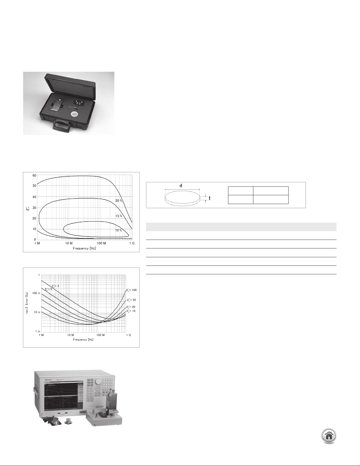
Typical permittivity (er´) Measurement accuracy
(@ thickness = 1 mm)
Typical loss tangent (tan δ) Measurement accuracy
(@ thickness = 1 mm)
E4991B with 16453A
Diameter ≥ 15 mm
Thickness 0.3 mm ~ 3 mm
Description P/N Qty.
Fixture holder 16453-01213 1
Load 16453-60021 1
Tweezers 8710-2081 1
Carrying case 16453-60011 1
Operation and service manual 16453-90010 1
49 | Keysight | Accessories Catalog for Impedance Measurements - Catalog
16454A magnetic material test
fixture
Terminal connector: 7 mm
Dimensions (approx.):
(Large test fixture) 30(D) x 35(H) [mm]
(Small test fixture) 24(D) x 30(H) [mm]
Weight (approx.):
(Large test fixture) 140 g
(Small test fixture) 120 g
Measurement accuracy (typical.):
Up to 3 GHz (7 mm): Material continued
Description: The 16454A is designed for accurate permeability measurements
of toroidal-shaped magnetic materials. Since the construction of this fixture
creates one turn around the toroid (with no magnetic flux leakage), the need of
winding a wire around the toroid is unnecessary. The following figure shows the
one-turn mechanism and how complex permeability is calculated from it.
Complex permeability is calculated from the inductance with and without the
toroid. When E4991B with option E4991B-002 is used as the measurement
instrument, direct readouts of complex permeability are possible. In addition, it
is furnished with a small and a large fixture to adapt to a wide range of sizes.
Applicable instruments: E4990A + 42942A*, E4991B with Opt. E4991B-002
* Option E4990A-120 is required
Frequency: 1 kHz to 1 GHz,
DC bias: –500 mA to +500 mA (max)
Operating temperature: –55 to 200°C
When Option E4991B-007 temperature characteristic test kit is used with
E4991B, the operating temperature range is between –55 and +150°C. The
temperature characteristic test kit is unavailable for the E4990A.
Material size: See figure below.
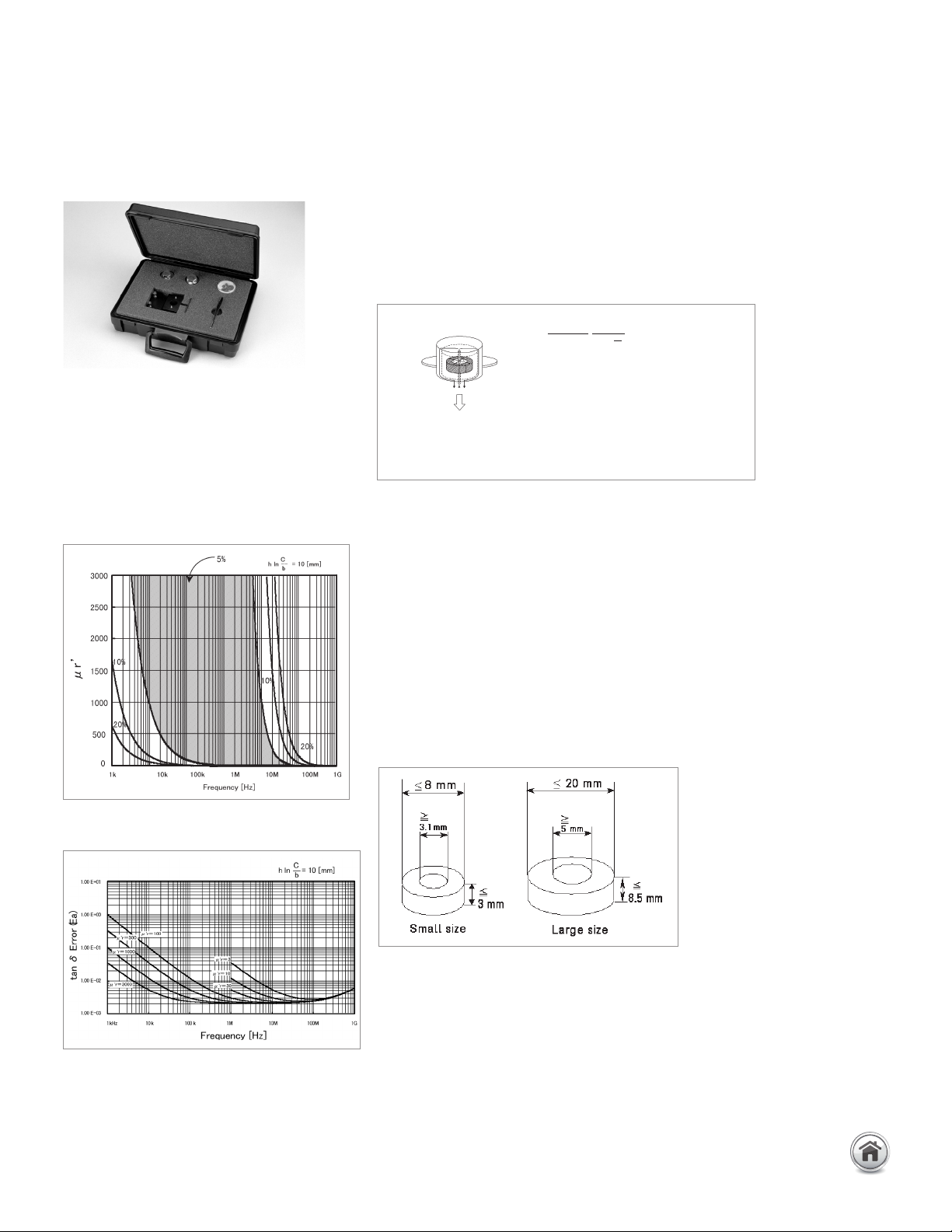
Typical permeability (µr') Measurement accuracy
(@ h* ln c/b = 10)
Typical loss tangent (tan δ) Measurement accuracy
(@ h* ln c/b = 10)
=
Zm - Zsm 2π
+ 1
jωµ
0
hln
c
b
E4991A/4291B/4294A
.
µ
..
Relative permeability
Zm Measured impedance with toroidal core
Zsm Measured impedance with toroidal core
µ
0
Permeability of free space
h Height of MUT (Material Under Test)
c Outer diameter of MUT
b Inner diameter of MUT
.
µ
.
.
Permeability measurement method of 16454A
Material size
50 | Keysight | Accessories Catalog for Impedance Measurements - Catalog
Up to 3 GHz (7 mm): Material continued
Placing the MUT on the test fixture as follows:
Furnished accessories:
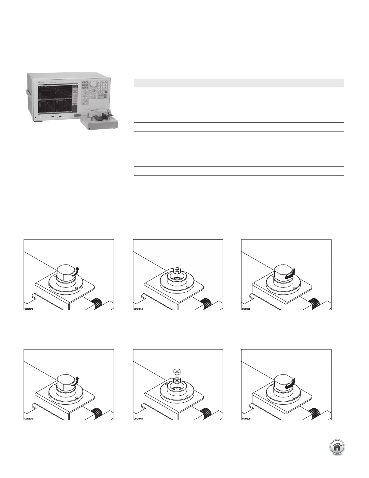
Compensation and measurement: Short compensation is required before measure-
ment. Short compensation is performed by only inserting the MUT holder into the test
fixture. After performing short compensation, the MUT is inserted into the fixture as
shown below.
Remove the cap of the fixture Place a MUT holder only in the fixture Replace the cap by screwing tightly
Remove the cap of the fixture Place a MUT onto the MUT holder and insert it
into the fixture.
Replace the cap by screwing tightly
Short compensation
E4991B with 16454A
Description P/N Qty.
Fixture holder 16454-00601 1
Tweezers 8710-2081 1
Screw, hex recess 0515-1050 1
Holder A 16454-25002 1
Holder B 16454-25001 1
Holder C (Without hole) 16454-25004 1
Holder D (With hole) 16454-25003 1
Holder case 1540-0622 1
Hex key (for replacing fixtures) 8710-1181 1
Carrying case 16454-60101 1
Operation and service manual 16454-90020 1
16454A magnetic material test fixture continued
51 | Keysight | Accessories Catalog for Impedance Measurements - Catalog