5965-4792.pdf - 第27页
1 6 451 B D ielectric test f ix ture continued Furnished acces sories: U p to 1 20 MHz ( 4- T ermi nal Pai r ): Ma teri al c onti nued Dimensions of unguarded e lectr ode Dim ensi ons o f fi x tur e as sem bly Descr ipti…
16451B Dielectric test fixture continued
Applicable instruments: E4980A/AL, E4981A, E4990A
Frequency: DC to 30 MHz
Maximum voltage: ±42 V peak max. (AC+DC)
Operating temperature: 0 to 55°C
Material size:
Up to 120 MHz (4-Terminal Pair): Material continued
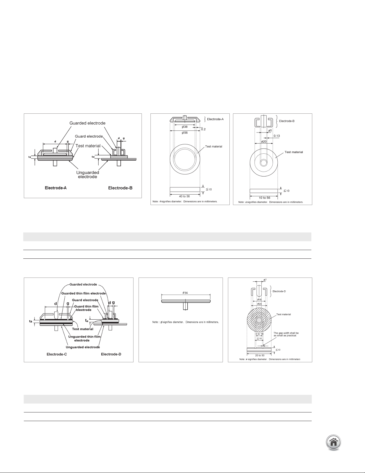
Electrodes for contacting electrode method (Rigid Metal
Electrode)
Material size for electrode-A Material size for electrode-B
Electrodes for contacting electrode method (Thin Film
Electrode)
Material size for electrode-C Material size for electrode-D
Equipped with Electrodes A and B for flat and smooth materials.
Equipped with Electrodes C and D for rough or extremely thin materials.
* diameter of applied thin film electrode
Electrode type Diameter of MUT Thickness of MUT Diameter of electrode Max. frequency
A 40 mm ~ 56 mm t ≤ 10 mm 38 mm 30 MHz
B 10 mm ~ 56 mm t ≤ 10 mm 5 mm 30 MHz
Electrode type Diameter of MUT Thickness of MUT Diameter of electrode Max. frequency
C 56 mm t ≤ 10 mm 5 ~ 50 mm 30 MHz
D 20 mm ~ 56 mm t ≤ 10 mm 5 ~ 14 mm 30 MHz
23 | Keysight | Accessories Catalog for Impedance Measurements - Catalog
16451B Dielectric test fixture continued
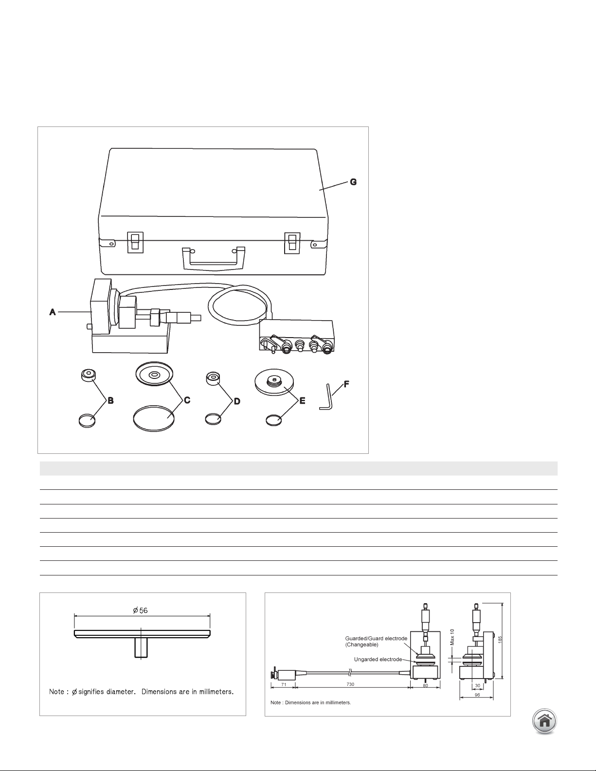
Furnished accessories:
Up to 120 MHz (4-Terminal Pair): Material continued
Dimensions of unguarded electrode
Dimensions of fixture assembly
Description P/N Qty.
Test Fixture including Electrode-A, unguarded electrode and cover N/A 1 A
Electrode-B and cover 16451-60013 1 B
Electrode-C and cover 16451-60012 1 C
Electrode-D and cover 16451-60014 1 D
Attachment for error compensation and cover 16451-60021 1 E
Hex key (for replacing electrodes) 5188-4452 1 F
Carrying Case 16451-60001 1 G
24 | Keysight | Accessories Catalog for Impedance Measurements - Catalog
16451B Dielectric test fixture continued
Compensation and measurement: There are three measurement methods for the
16451B. They are the Contacting Electrode Method (used with 16451B’s rigid metal
electrode, without any electrodes on the material under test), the Contacting Electrode
Method (used with thin film electrodes made on the material under test), and the Non-
Contacting Electrode (Air Gap method). Select the suitable measurement method and
the suitable electrode for the material under test according to the following table.
Summary of measurement method
Open and short compensations are recommended in combination with the cable length
compensation before measurement. When measuring above 5 MHz with the E4990A,
load compensation is also recommended. First, set the instrument’s cable length
compensation function to 1 m. Then, open and short compensation is performed by
using the furnished electrode attachment. Load compensation is performed, by prepar-
ing a working standard. After performing open, short and load compensations, the MUT
is sandwiched by the parallel electrodes and the capacitance is measured. Relative
permittivity is calculated from the measured capacitance in the following manner:
t
a
× C
p
εr�=
d
π × (—)
2
× ε
o
2
εr� : Relative permittivity
C
p
: Capacitance (measurement data)
o
: 8.854 × 10
–12
[F/m]
t
a
: Average thickness of test material
d : Diameter of guarded electrode
Up to 120 MHz (4-Terminal Pair): Material continued
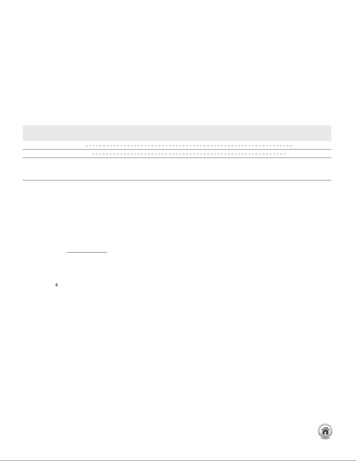
Measurement
method
Contacting electrode method (used with
rigid metal electrode)
Contacting electrode method (used
with thin film electrode)
Non-contacting electrode method
Accuracy Low > High
Operation Simple > Complex
Applicable
materials
Thick, solid and smooth materials Materials on which thin film can
be applied without changing its
characteristics
Thick, and soft materials Rough
materials also
25 | Keysight | Accessories Catalog for Impedance Measurements - Catalog