5965-4792.pdf - 第49页
1 61 9 8A Bot tom electrode S MD test f ix ture T erminal connector : 7 mm DUt c onnec tio n: 2- Te r m i n a l Dimensions ( appr o x.): 1 4 5 (W ) × 8 0 (D ) × 1 1 0 (H) [ mm] Wei gh t (ap pr ox .): 87 0 g ( w ith we ig…
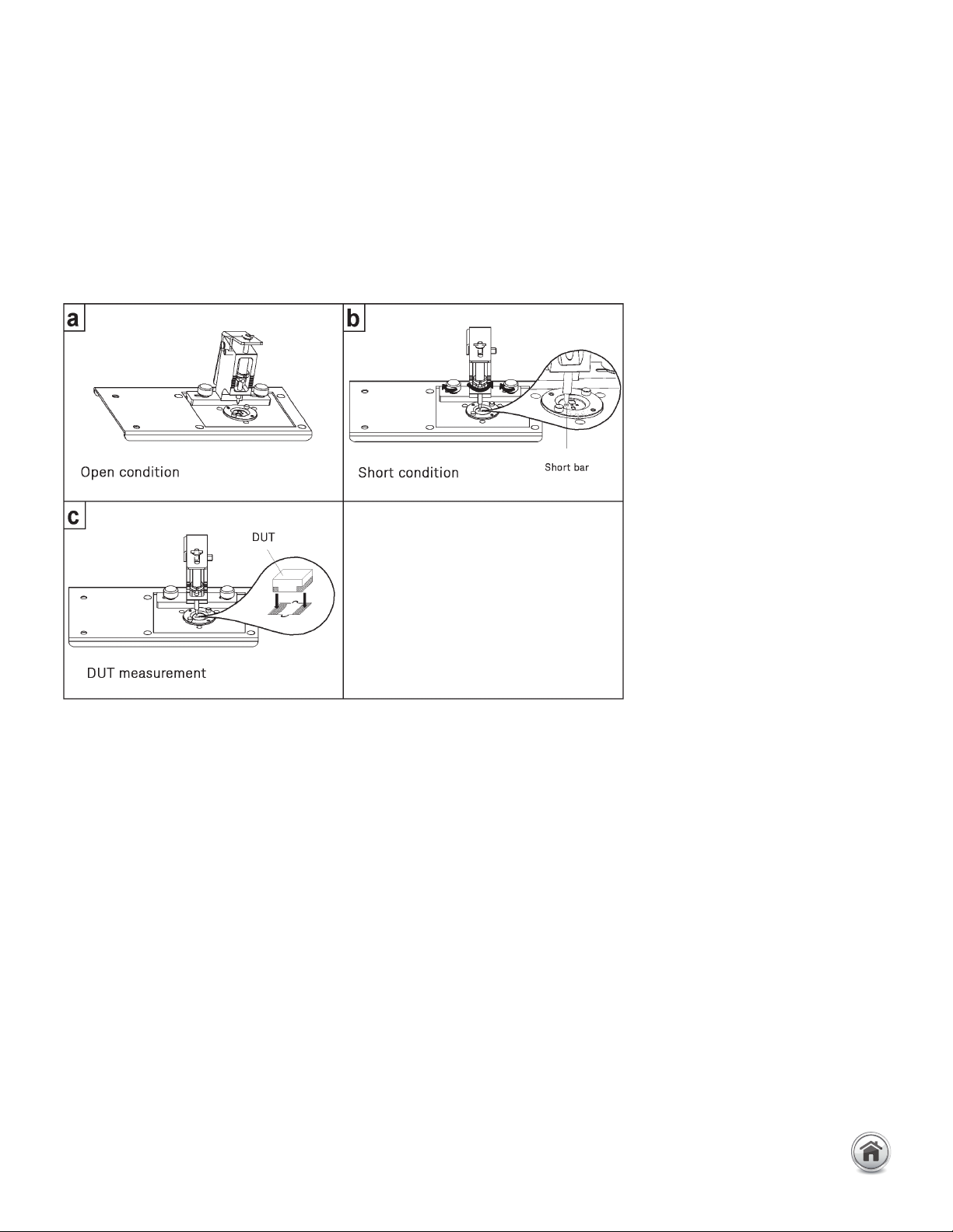
instrument first. Next, open compensation is performed by not placing anything in the
device insertion hole. Short compensation is performed by placing the furnished shorting
device in the device insertion hole. After performing open and short compensations in
combination with the electrical length compensation, the DUT is inserted into the device
insertion hole. Once the measurement of the DUT is complete, remove the DUT from the
fixture. The following figures show how compensation and measurement is performed.
Up to 3 GHz (7 mm): SMD continued
Compensation and measurement
16197A Bottom electrode SMD test fixture continued
45 | Keysight | Accessories Catalog for Impedance Measurements - Catalog
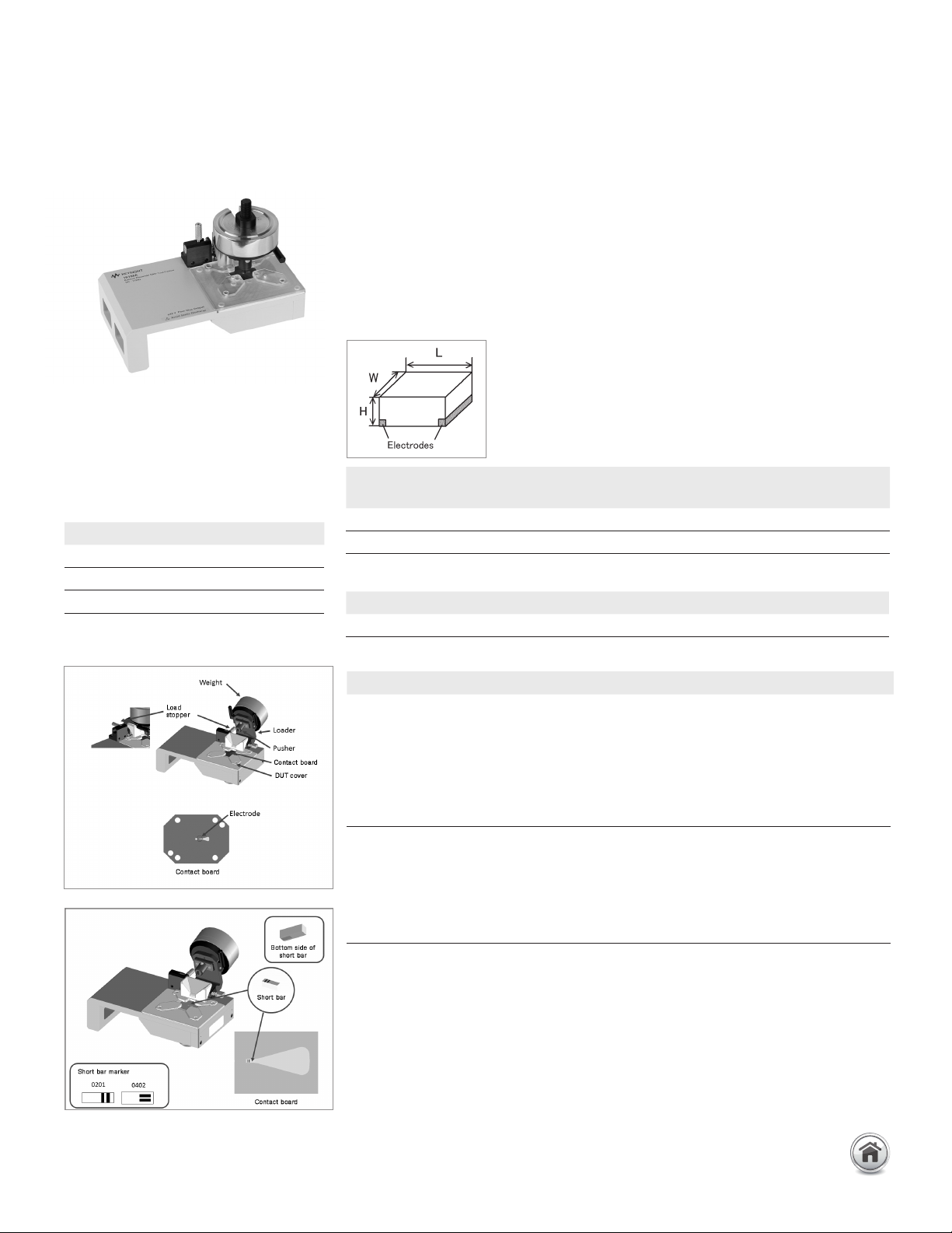
16198A Bottom electrode SMD
test fixture
Terminal connector: 7 mm
DUt connection: 2-Terminal
Dimensions (approx.):
145 (W) × 80 (D) × 110 (H) [mm]
Weight (approx.): 870 g (with weight of
300 g)
Additional error:
Description: This test fixture is designed for impedance evaluations of bottom electrode
SMDs. It achieves stable frequency characteristics up to 3 GHz and provides highly
repeatable measurements. This test fixture supports two SMD sizes, 0201 (mm)/
008004 (inch) and 0402 (mm)/01005 (inch).
Applicable instrument: E4982A, E4991B, E5061B-3L3/3L4/3L5 with Opt. 005 + 16201A
Frequency: DC to 3 GHz
Maximum voltage: ±40 V peak max. (AC +DC)
Operating temperature: –55 to +85°C
DUT size: See figure and table below:
Standard option
SMD size code
Applicable SMD size
L [mm] W [mm] H [mm]
0402 (mm)/01005 (inch) (0.38 to 0.42) ±0.02 (0.18 to 0.22) ±0.02 ≥ 0.11
0201 (mm)/008004 (inch) (0.2 to 0.25) ±0.013 (0.1 to 0.125) 0.013 ≥ 0.1
Furnished Accessory
Description P/N
Cleaning rod 5182-7586
f: frequency [GHz]
Up to 3 GHz (7 mm): SMD continued
Error factor Formula
Proportional error 1.2 x f
2
[%]
Open repeatability 5 + 40 x f [μS]
Short repeatability 60 + 125 x f [mΩ]
Optional accessories
Standard set P/N Qty.
Standard set, 0201 16198A-100
Contact board (Guide PCA 0201 70 micrometer) 1
Contact board (Guide PCA 0201 100 micrometer) 1
0201 Short bar 5-piece set 1
Weight 50 g 1
Weight 100 g 1
Weight 200 g 1
Standard set, 0402 16198A-200
Contact board (Guide PCA 0402 100 micrometer) 1
0402 Short bar 5-piece set 1
Weight 50 g 1
Weight 100 g 1
Weight 200 g 1
Note: A standard set of either 0201 or 0402 can be ordered, but not both.
If necessary, the parts can be ordered individually.
46 | Keysight | Accessories Catalog for Impedance Measurements - Catalog
Optional accessories P/N
Contact board (Guide PCA 0201, 70 micrometer) 16198A-101
Contact board (Guide PCA 0201, 100 micrometer) 16198A-102
Contact board (Guide PCA 0402, 100 micrometer) 16198A-201
0201 Short bar 5-piece set 16198A-110
0402 Short bar 5-piece set 16198A-210
Weight 50 g 16198A-520
Weight 100 g 16198A-521
Weight 200 g 16198A-522
Carrying case 16198A-530
Torque driver 16198A-531
User manual English 16198A-ABA
User manual Japanese 16198A-ABJ
Retrofit/service parts P/N
Contact board (Guide PCA 0201, 70 micrometer) 16198AU-101
Contact board (Guide PCA 0201, 100 micrometer) 16198AU-102
Contact board (Guide PCA 0402, 100 micrometer) 16198AU-201
Contact board 8-piece set (Guide PCA 0201, 70 micrometer) 16198AU-103
Contact board 8-piece set (Guide PCA 0201, 100 micrometer) 16198AU-104
Contact board 8-piece set (Guide PCA 0402, 100 micrometer) 16198AU-202
0201 Short bar 5-piece set 16198AU-110
0402 Short bar 5-piece set 16198AU-210
Weight 50 g 16198AU-520
Weight 100 g 16198AU-521
Weight 200 g 16198AU-522
Carrying case 16198AU-530
Torque driver 16198AU-531
Pusher unit 16198AU-540
DUT cover ass’y 16198AU-544
Connector APC3.5 16198AU-545
Up to 3 GHz (7 mm): SMD continued
16198A Bottom electrode SMD test fixture continued
47 | Keysight | Accessories Catalog for Impedance Measurements - Catalog