00198281-02_JG SmartFeeder 24-104 mm X_EN.pdf - 第24页
Operating the Feeder Module - Display of Error and Warning States 24 www.asm-smt.com

Operating the Feeder Module - Display of Error and Warning States
23
www.asm-smt.com
1.19 Display of Error and Warning States
Operating state 7 segment display Status LED
Position Display val-
ues
Error state "foil peel"
The foil is stretched, the tape drive has transported but the foil removal
device was not activated.
At the top
At the bottom
E r (error)
F o. (foil, .)
Red
Error state "CAN Bus error"
Error at the CAN Bus interface.
At the top
At the bottom
E r (error)
C A (CAN
bus)
Red
Error state „Removal handle extended“
After logging on the feeder module to the FCU, the removal handle is still
extended.
At the top
At the bottom
H A (handle)
o u (out)
Red
Error state "Application invalid"
The application software is invalid or not loaded.
At the top
At the bottom
Switched off
Switched off
Red
Flashing
Error state "Voltage supply too low"
When the feeder module is switched on, the voltage supply is too low.
At the top
At the bottom
Switched off
Switched off
Orange
Warning "Function cannot be performed"
The function triggered on the operator panel cannot be performed at
present.
At the top
At the bottom
- - Flashing
- - Flashing
Orange
More error states and their fixes can be found in the relevant service and user guides.

Operating the Feeder Module - Display of Error and Warning States
24
www.asm-smt.com
Splicing - Required Tools and Materials
25
www.asm-smt.com
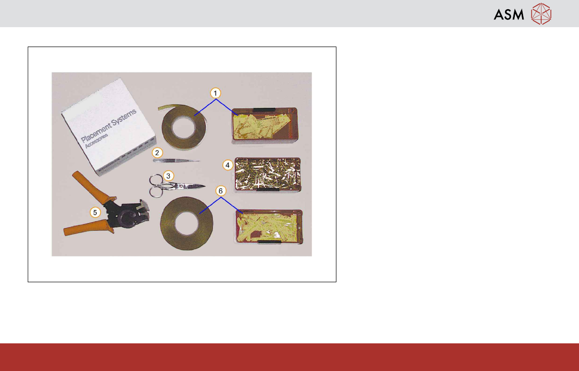
2 Splicing2.1 Required Tools and Materials
These tools and materials are required for tape
splicing:
1. Adhesive tape (small)
2. Tweezers
3. Scissors
4. Splicing rivets
5. Splicing tool
6. Adhesive tape (large)