00198281-02_JG SmartFeeder 24-104 mm X_EN.pdf - 第6页
Operating the Feeder Module - Front side 6 www.asm-smt.com 1.2 Front side 1. Sliding guide 2. Energy and data interface (EDIF) 3. Centering pin at front 4. Pickup window actuator 5. Pickup window 6. Removal edge 7. Splic…

Operating the Feeder Module - Important Note for ASM Setup Center
5
www.asm-smt.com
1 Operating the Feeder Module1.1 Important Note for ASM Setup Center
This document describes the most frequent procedures used to operate your 24-100mm X SmartFeeder.
NOTICE
ASM Setup Center
If you are also using ASM Setup Center, the procedures you follow may differ from those described in this docu-
ment.
For this reason, make sure you read and follow the detailed instructions in the ASM Setup Center User Guide.
The following procedures are affected by these differences:
– Feeder module setup and tear down.
– Feeder module setup verification.
– Feeder module refill.
Operating the Feeder Module - Front side
6
www.asm-smt.com
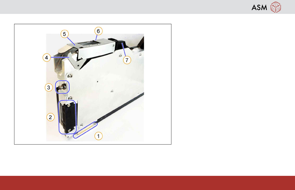
1.2 Front side
1. Sliding guide
2. Energy and data interface (EDIF)
3. Centering pin at front
4. Pickup window actuator
5. Pickup window
6. Removal edge
7. Splice sensor (or dummy)
Operating the Feeder Module - Rear side
7
www.asm-smt.com
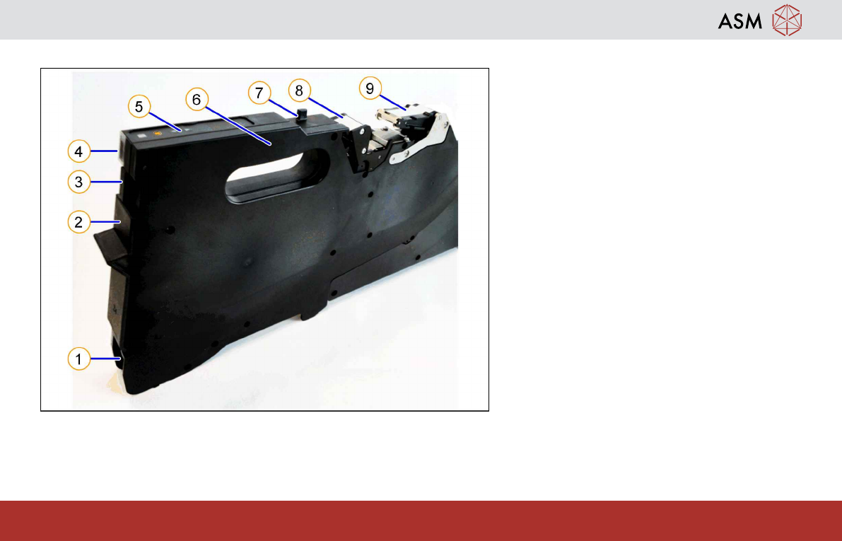
1.3 Rear side
1. Tape duct with spring
2. Foil disposal flap
3. Removal handle
4. Status display
5. Operator panel
6. Handle
7. Rear centering pin
8. Foil removal rocker
9. Foil rocker