ENA-X and ENA Series Vector Network Analyzers.pdf - 第9页
9 Calibration O ptions Description For E5080B ENA For E5081A ENA -X Additional I nformation ISO 17025 compli ant calibratio n E5080B - 1A7 E5081A - 1A7 Provides a co mplete set of measur ements which tests the unit t o m…

8
Analog input and output (E5080B and E5081A. With Option 175)
Option 175 adds analog input and output ports with BNC female connectors on the rear panel of the analyzer
to enable DC measurements with the E5080B. Two integrated variable DC sources provide ±10 VDC with
maximum current of 200 mA. Synchronized DC voltage sweep is performed using the VNA’s firmware.
For more comprehensive analysis, four analog inputs with BNC female connectors are provided to allow
sensing of DC voltages from the DUT.
Device Test I/O (E5080B and E5081A)
Device test I/O with a 25-pin D-sub connector on the rear panel of the analyzer allows users to control the
Device Under Test (DUT) directly with serial or parallel digital interface. Signals from the I/O are applied
to select operation modes of the RF front-end module which integrates power amplifiers, switches, low
noise amplifiers, duplexers, or filters in a single component.
The device test I/O has two independent 8-bit digital I/Os (DIOs). Each 8-bit DIO can provide either 8-bit
parallel signals or 4-channels of RFFE-like interface. Output DC voltage or clock rate (25 MHz maximum)
are selectable according to the specification of DUTs.
Quick and easy setup of DUT control signals can be done with the VNA’s firmware, and the operation of
the device test I/O is synchronized with the measurement sweep of the analyzer.
Application I/O (E5080B and E5081A)
Application I/O with a 15-pin D-sub connector on the rear panel of the analyzer provides required signals
for synchronized measurements using the analyzer and external peripherals such as pulse generators,
pulse modulators, RF switches for NF measurements, or signal generators.
Y1721A Option 001 I/O adapter for application I/O of the analyzer is recommended if using an external
pulse generator. N1966A pulse I/O adapter included in Y1721A Option 001 enables coaxial connections
between the Application I/O D-sub connector on the rear panel of the analyzer and the coaxial inputs and
outputs of external pulse generators and external pulse modulators. Coaxial connectors are SMB male. A
connector saver (P/N: Z2342-37605) and hex standoff (P/N: 0380-5932) in Y1721A Option 001 are
required for the connection of the analyzer and N1966A.

9
Calibration Options
Description
For E5080B ENA
For E5081A ENA-X
Additional Information
ISO 17025 compliant
calibration
E5080B-1A7
E5081A-1A7
Provides a complete set of measurements which
tests the unit to manufacturer’s published
specifications. Includes calibration label, ISO
17025 calibration certificate and data report, and
measurement uncertainties and guardbands on
all customer specifications. Conforms to ISO
17025 and ISO 9001.
ANSI Z540
compliant calibration
E5080B-A6J
N/A
Provides a complete set of measurements which
tests the unit to manufacturer’s published
specifications. Includes pre- and post-adjustment
data and measurement uncertainty information
compliant with the ANSI/NCSL Z540 standard.
Accessories
Description
For E5080B ENA
For E5081A ENA-X
Additional Information
Rack mount kit for
installation without
handles
E5080B-1CM
E5081A-1CM
Adds a rackmount flange kit (5063-1543) and a
rail kit (E3663AC) for use without handles.
Rack mount kit for
installation with
handles
E5080B-1CP
E5081A-1CP
Adds handles, a rack mount flange kit (5063-
1555), and a rail kit (E3663AC) for use with
handles.
Add keyboard
E5080B-181
E5081A-181
Add mouse
E5080B-182
E5081A-182
Solid State Drive
(SSD) spare kit
E5080BU-180,
E5080BU-181
1
, or
E5080BU-182
2
E5081AU-180,
E5081AU-181
3
, or
E5081AU-182
4
Visit web sites (E5080B upgrade kits / E5081A
upgrade kits) for more details.
1. Spare SSD with Windows 10 OS. For the E5080B with serial-number prefixes of MY592/SG592 or lower, order the E5080BU-
180. For the E5080B with series-number prefixes of MY593/SG593 or greater, order the E5080BU-181.
2. Spare SSD with Windows 11 OS. It is not compatible with E5080B with serial-number prefixes of MY591-MY595 or SG591-
SG595.
3. Spare SSD with Windows 10 OS. For the E5081A with serial-number prefixes of MY632/SG632 or lower, order the E5081AU-
180. For the E5081A with series-number prefixes of MY633/SG633, order the E5081AU-181.
4. Spare SSD with Windows 11 OS. It is not compatible with E5081A with serial-number prefixes of MY631-MY633 or SG631-
SG633.
10
E5081A ENA-X with Configurable Test Set
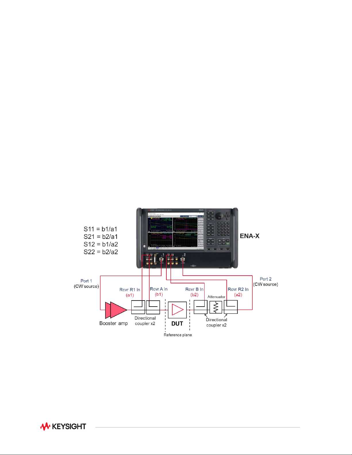
The E5081A ENA-X comes with a configurable test set on ports 1 and 2 to allow for flexible setup of test
systems by integrating with external components
1
such as booster amplifiers, attenuators, or directional
couplers. This functionality combined with modulated signal analysis allows you to characterize highly
integrated components with a single connection.
High-Power S-Parameter Tests
One example using the E5081A with configurable test set is S-parameter measurements of high-power
devices. When you need an input level higher than the analyzer’s source can provide, booster amplifiers
are necessary to increase the power level incident upon the DUT. However, the reference signal is
measured before the booster amplifier with a standard configuration of a 2-port VNA, and temperature
drift or high reverse isolation of a booster amplifier will prevent accurate reflection measurements of the
DUT’s input.
A typical configuration for high-power measurements with the 2-port E5081A is shown. Reflected and
transmitted signals of the DUT are detected with all the logical receivers, and the VNA firmware provides
measured high-power S-parameters.
External components should be selected based on their high-power limits or frequency range
specifications. Be sure that these components can handle the output power level of the booster amplifier.
1. External components are not included with the E5081A. Must be purchased separately.