4OM-1011-002.pdf - 第119页
0305-001 Tg0860-PM-MM 6.5 HEAD OFFSET Display • This display allows teaching the head of fset data. The head offset data is used to correct the deviation between the component recognition position and the placement posit…
0305-001 Tg0860-PM-MM
Operation Procedure
• Required Items
Nozzle: 4 pieces of “MF01”, “MF02” or “MA06”
Jig Component: Teaching Plate (Component Recognition Offset Jig)
(Standard Accessory Part)
(1) Set either “MF01”-, “MF02”- or “MA06”-type nozzle in the nozzle
stocker.
(2) Attach the jig component (the teaching plate (component recognition
offset jig)) to the position where the teaching plate is attached.
Note: The printed side of the component recognition offset jig should
face downward.
(3) Check the followings.
• Check that the machine is powered.
• Check that the supply cover is completely closed.
(4) Attach either “MF01”-, “MF02”- or “MA06”-type nozzle to the ob-
jective placement head for teaching at the “MANUAL NOZZLE
CHANGE OPERATION” display.
(5) Designate the camera to be used for teaching.
(6) Select the [ALL BEAM HEADS ZERO [MOVE]] key and press the
[MOVE] button to zero all beam heads.
(7) To specify the gain and level, use the “GAIN・LEVEL” display.
Note: In normal cases, set “DISABLE” in the “DESIGNATE” data
box.
(8) Select the item to be taught and press the [MOVE] button.
The machine starts the teaching operations.
The following series of teaching operations are performed automati-
cally.
The nozzle picks up the teaching plate from the place where the teaching
plate is attached.
↓
The placement head moves to the component recognition camera position.
↓
The jig component is recognized with the component recognition camera.
(Posture at 4 Directions: 0°, 90°, 180°, and 270°)
↓
The teaching plate is returned to the original place (the place where it was
attached)
3-67
6.4 HEAD CENTER OFFSET Display
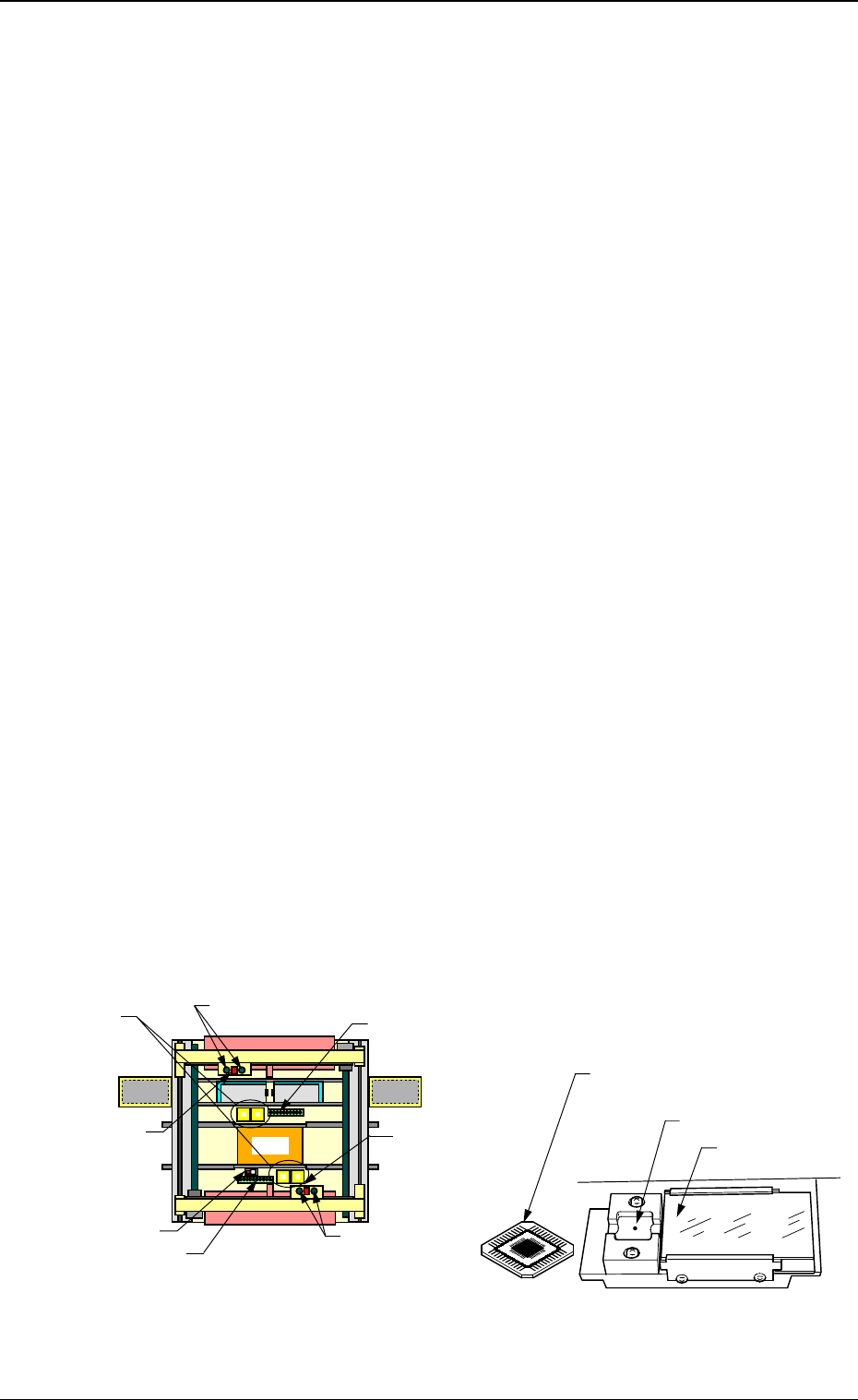
Beam A Side
Teaching Plate
(Component Recognition Offset Jig)
Position of Teaching Plate
Back Light Stage
Magnified View of Teaching Plate Section
Fig. 4C114
Teaching Plate Section
Component Rec-
ognition Camera
Nozzle Stocker
Placement Head
Nozzle Stocker
Placement Head
Beam B Side
Overall Top View
P.E.C. Recogni-
tion Camera
P.E.C. Recognition
Camera
0305-001 Tg0860-PM-MM
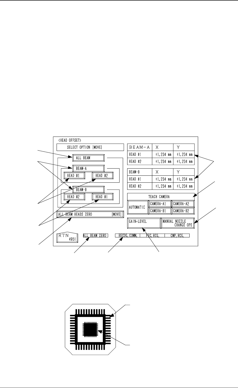
6.5 HEAD OFFSET Display
• This display allows teaching the head offset data.
The head offset data is used to correct the deviation between the component
recognition position and the placement position caused due to the deviation
of straightness (skew) of the up/down axis.
The offset values are calculated by recognizing the printed pattern on the jig
component (the teaching plate (component recognition offset jig)) picked
up by a nozzle with both component recognition and P.E.C. recognition cam-
eras.
Note: Follow the teaching procedures in the specified order. Otherwise, some
trouble (such as inaccurate component placement, frequent mechani-
cal errors, etc.) will arise.
When the [HEAD OFFSET] key is pressed at the “TEACH OFFSET” display,
the following display appears on the screen.
Teaching Plate (Component Recognition Offset Jig: JG0085)
(Standard Accessory Part)
Note: Handle this fragile jig very carefully.
• Two types of patterns are printed through vapor deposition on the glass for
positional calculation.
*7
*6
*10
*2
*1
*3
*4
*3
*8
*9
*5
3-68
6.5 HEAD OFFSET Display
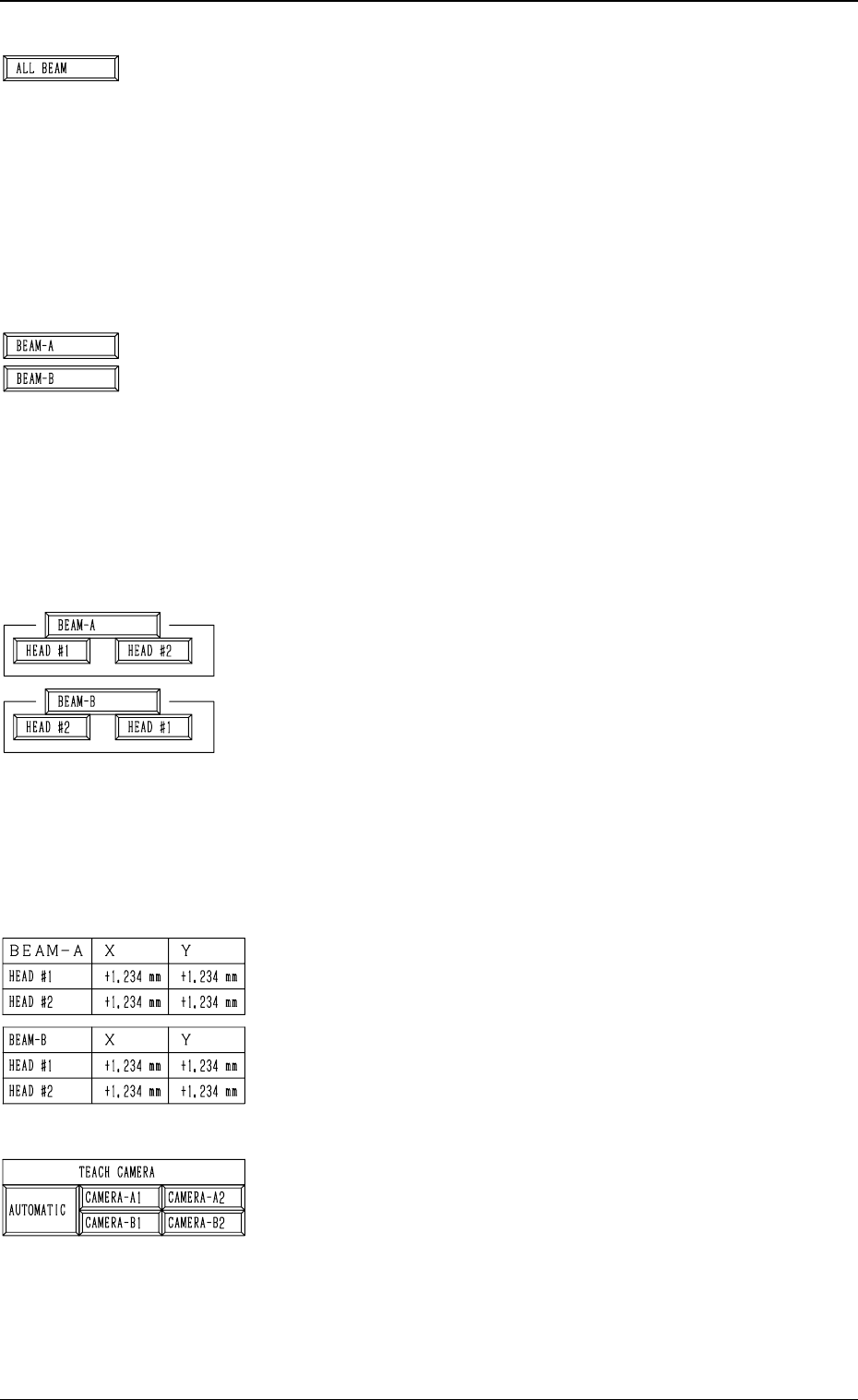
Fig. 4C115
Pattern to be captured by the
component recognition camera
Pattern to be captured by the
P.E.C. recognition camera
Fig. 4C116
0305-001 Tg0860-PM-MM
*1 [ALL BEAM] Key
The machine performs the teaching operation of the head
offset data for both heads on Beams A and B in the se-
quential order.
When this key is selected and the [MOVE] button is pressed,
the machine starts the teaching operation.
The keys with a red frame can not be selected because the
head skip setting has been performed for such keys.
Note: Before performing the teaching operations, zero
both beams.
*2 [BEAM-A] and [BEAM-B] Keys
The machine performs the teaching operations of the head
offset data of both heads on Beam A or B.
When the [BEAM-A] or the [BEAM-B] key is selected
and the [MOVE] button is pressed, the machine performs
the teaching operations.
The keys with a red frame can not be selected because the
head skip setting has been performed for such keys.
Note: Before performing the teaching operations, zero
both beams.
*3 [HEAD #1] and [HEAD #2] Keys in “BEAM-A” Group
Box and [HEAD #2] and [HEAD #1] Keys in “BEAM-B”
Group Box
The machine performs the teaching operation of the head
offset data.
When one of the above-described keys is selected and the
[MOVE] button is pressed, the machine starts teaching the
offset data related to the selected head #.
The keys with a red frame can not be selected because the
head skip setting has been performed for such keys.
Note: Before performing the teaching operations, zero
both beams.
*4 Offset Data
Shown is the head offset data of each head on Beams A and
B.
*5 TEACH CAMERA
A camera can be designated for teaching operations.
“AUTOMATIC”, “CAMERA-A1”, “CAMERA-A2”,
“CAMERA-B1”, or “CAMERA-B2” can be selected.
When “AUTOMATIC” is selected, a camera is automati-
cally selected for teaching operations.
When one of the above-described options except for “AU-
TOMATIC” is selected, the machine performs the teach-
ing operations with the designated camera.
3-69
6.5 HEAD OFFSET Display
Fig. 4C117
Fig. 4C118
Fig. 4C119
Fig. 4C120
Fig. 4C121