4OM-1011-002.pdf - 第266页
0305-001 Tg0860-PM-MM 1. Hierarchical Structure of Machine Set-Up Displays Machine set-up operation is described along with the following hierarchical structure. The numbers in ( ) show item Nos. to be referred to. 4-1 1…

0305-001 Tg0860-PM-MM
4-B
0305-001 Tg0860-PM-MM
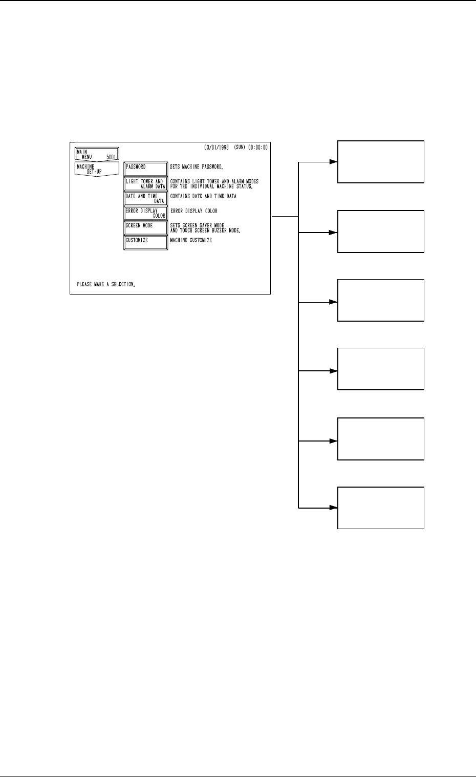
1. Hierarchical Structure of Machine Set-Up Displays
Machine set-up operation is described along with the following hierarchical
structure.
The numbers in ( ) show item Nos. to be referred to.
4-1
1. Hierarchical Structure of Machine Set-Up Displays
PASSWORD
(3. in Section 4)
LIGHT TOWER
AND ALARM
DATA
(4. in Section 4)
DATE AND
TIME DATA
(5. in Section 4)
ERROR
DISPLAY
COLOR
(6. in Section 4)
SCREEN MODE
(7. in Section 4)
CUSTOMIZE
(8. in Section 4)
Fig. 4D1
0305-001 Tg0860-PM-MM
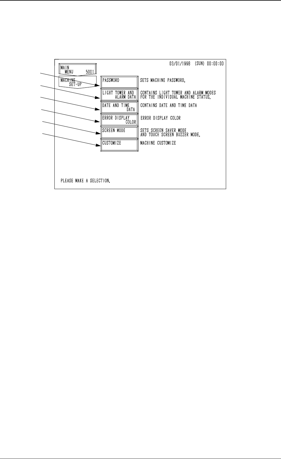
2. MACHINE SET-UP Display
When the [MACHINE SET-UP] key is pressed at the “MAIN MENU” dis-
play, the following display appears on the screen.
*1 When this key is pressed, the “PASSWORD” display appears on the screen.
Three kinds of passwords and an effective range of each password can be
set. Deleting or changing data on the machine side by mistake can be avoided
by setting and managing a password.
*2 When this key is pressed, the “LIGHT TOWER AND ALARM DATA”
display appears on the screen.
The “ON, OFF, or FL (flashing)” can be selected for the tower lights ac-
cording to the machine status (automatic operation mode, error condition,
P.C.B. transfer waiting mode, etc.).
The “ON (CONTINUOUS), OFF, ON AND OFF, or OPTIONAL ALARM”
can also be selected for the alarm buzzer according to the machine status
(error condition, shortage of component, alternate feeder, etc.).
*3 When this key is pressed, the “DATE AND TIME DATA” display appears
on the screen.
Date and time (calendar function) can be set.
*4 When this key is pressed, the “ERROR DISPLAY COLOR” display ap-
pears on the screen.
The background and letter colors of the error information box can be changed
according to one of the several optional combinations.
*5 When this key is pressed, the “SCREEN MODE” display appears on the
screen.
This function is used to turn the touch screen buzzer “ON” or “OFF” and
set the screen saver mode. Settings such as date (three kinds of expres-
sions), Japanese/English, metric/inch system can also be controlled.
Note: This display can’t be opend when the machine is working or
communicateing with the programming device (option).
*6 When this key is pressed, the “CUSTOMIZE” display appears on the screen.
This function is used to automatically delete all component library data
which is not used by the machine after the corresponding pattern program
data is deleted.
4-2
2. MACHINE SET-UP Display
Fig. 4D2
*1
*2
*3
*4
*5
*6