4OM-1011-002.pdf - 第130页
0305-001 Tg0860-PM-MM *1 1 SELECT TEACH CAMERA A component recognition camera can be designated for teaching the rotational shaft angle of fset data. Press the [CAMERA-A1], the [CAMERA-A2], the [CAMERA-B1], or the [CAMER…
0305-001 Tg0860-PM-MM
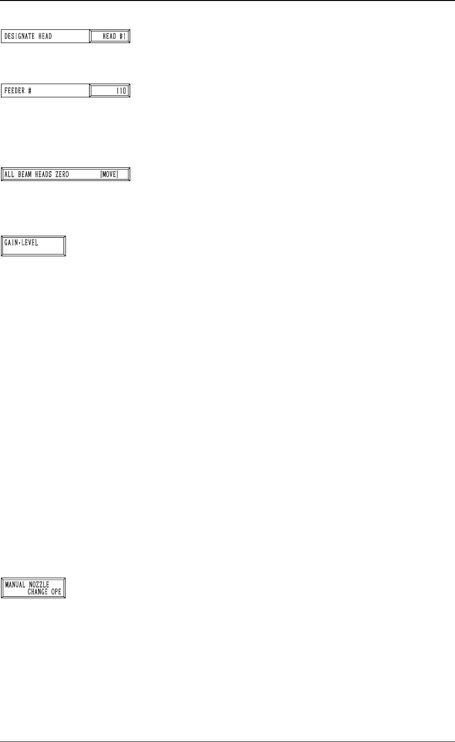
*6 DESIGNATE HEAD
This allows designating the head where the special jig nozzle
is picked up.
Set either “HEAD #1” or “HEAD #2” in the data box.
*7 FEEDER #
This allows designating the feeder No. to determine the
place where the special jig nozzle is attached by hand.
The head moves to the feeder designated when the nozzle
is attached or collected.
*8 [ALL BEAM HEADS ZERO [MOVE]] Key
Both Beams A and B are zeroed.
When this key is selected and the [MOVE] button is pressed,
the zeroing operation starts.
*9 [GAIN・LEVEL] Key
When this key is pressed, the “GAIN・LEVEL” display (Fig.
4C70) appears on the screen.
These parameters are used to set amplifications at which
the image signals of the image taken by the component rec-
ognition camera is converted into the picture information
representing brightness.
Parameters are set as the offset values for camera reference
gain and level.
Normal Fixed Value: ± 0
• When “ENABLE” is set in the “DESIGNATE” data box
at the “GAIN・LEVEL” display, be sure to set param-
eters in the “GAIN” and “LEVEL” data boxes.
The set parameters are used for P.E.C. recognition.
When “DISABLE” is set in the data box, the standard
parameters are set in the “GAIN” and “LEVEL” data
boxes.
• The lower the gain is, the bigger the contrast becomes.
• The lower the level is, the brighter the whole view be-
comes.
Note: Teaching operations are performed through compo-
nent recognition. Incorrect gain and level parameters
lead to the adverse result of teaching operations, caus-
ing some trouble.
*10 [MANUAL NOZZLE CHANGE OPE] Key
When this key is pressed, the “MANUAL NOZZLE
CHANGE OPERATION” display (Fig. 4C85) appears on
the screen.
The set parameters are used to store the nozzle before
coarse angle teaching operation or pick up the special jig
nozzle for angle teaching operation.
Refer to “9. Manual Nozzle Change Operation of Section
4 in Volume 1” for details.
3-78
6.7 HEAD ROTATION OFFSET Display
Fig. 4C146
Fig. 4C147
Fig. 4C148
Fig. 4C149
Fig. 4C150
0305-001 Tg0860-PM-MM
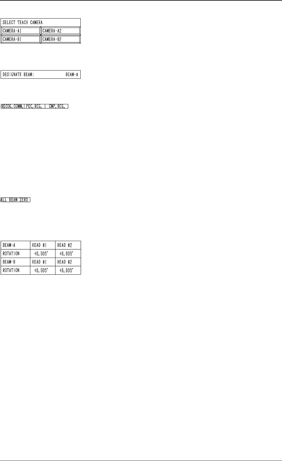
*11 SELECT TEACH CAMERA
A component recognition camera can be designated for
teaching the rotational shaft angle offset data.
Press the [CAMERA-A1], the [CAMERA-A2], the
[CAMERA-B1], or the [CAMERA-B2] key.
*12 DESIGNATE BEAM
Shown is the beam selected to pick up the special jig nozzle
which was designated in *5.
*13 RECOG. COMM.
When “DISABLE” is set in the “P.E.C.” and “COMPO
NENT RECOGNITION” data boxes at the “TEST
MODE” display, the background color of “P.E.C. RECOG.”
and “COMP. RECOG.” becomes light red. (No background
color in normal cases)
In this case, the recognition processing is not made even if
the teaching operations are performed. Therefore, the re
sults of various teaching operations are not reflected on
the offset data.
*14 ALL BEAM ZERO
When all beams are zeroed completely, the background
color of "ALL BEAM ZERO" turns green. Otherwise, the
background has no color.
*15 Offset Data
Shown is the rotational angle offset data for each head.
This function is used for housing the nozzle before the
rough angle teaching is performed or for special jig
nozzle pick- up during the angle teaching.
For the further details of operation, refer to “9. Manual
Nozzle Change Operation of Section 4 in Volume 1”.
3-79
6.7 HEAD ROTATION OFFSET Display
Fig. 4C151
Fig. 4C152
Fig. 4C153
Fig. 4C154
Fig. 4C155
0305-001 Tg0860-PM-MM
Operation Procedure
(1) Coarse Angle Teaching Operation
Follow the steps below to perform the coarse angle teaching operation
such that the nozzle can be picked up from the nozzle stocker.
(1.1) The dummy data for the special jig nozzle can be registered at the
“NOZZLE LIBRARY INFO” display. (Hierarchical Sequence:
“DATA EDIT” Display → “NOZZLE LIBRARY INFO” Display)
Enter the following parameters.
NOZZLE ID: JG01
SHAPE: ROUND or RECTANGLE
NOZZLE LENGTH: 19.0 mm
NOZZLE OUTER SIZE X: 10.0 mm
NOZZLE OUTER SIZE Y: 10.0 mm
It is not necessary to set the other parameters.
Refer to “Section 8 Nozzle Type Data in Volume 2” for details.
(1.2) Register “JG01” individually for both nozzle stockers A and B at
the “NOZZLE STOCKER DATA” display. (Hierarchical Sequence:
“DATA EDIT” Display → “NOZZLE STOCKER DATA” Display)
Refer to “Nozzle Stocker Data of Section 7 in Volume 2” for de-
tails.
(1.3) Open the “HEAD ROTATION OFFSET” display. (Hierarchical Se-
quence: “SPECIAL SEL.” Display → “TEACH OFFSET” Display
→ “HEAD ROTATION OFFSET” Display)
(1.4) Press the [MANUAL NOZZLE CHANGE OPE] key at the “HEAD
ROTATION OFFSET” display (Fig. 4C139). The “MANUAL
NOZZLE CHANGE OPERATION” display (Fig. 4C85) appears
on the screen. Return all nozzles on the head to the nozzle stocker.
Refer to “9. Manual Nozzle Change Operation of Section 4 in Vol-
ume 1” for details.
(1.5) Designate the beam and the head to be used for teaching operations
by setting parameters in the “DESIGNATE BEAM” and “DESIG-
NATE HEAD” data boxes at the “HEAD ROTATION OFFSET”
display (Fig. 4C139).
Designate the feeder No. (the feeder position where the nozzle must
be attached by hand) in the “FEEDER #” data box.
Note:
“110 to 130” must be set in the data box when “BEAM-A”
is entered in the “DESIGNATE BEAM” data box and “210
to 230
” when “BEAM-B” is set in the “DESIGNATE
BEAM
” data box.
(1.6) When the [PICK UP NOZZLE] key is selected and the [MOVE]
button is pressed, the selected head moves to the designated feeder
# position.
(1.7) Set the [OPERATION/SET UP] switch to the “SET UP” side and
press the [READY] button for the pertinent beam to unlock the
supply cover.
Open the supply cover and attach the special jig nozzle to the head.
3-80
6.7 HEAD ROTATION OFFSET Display
Fig. 4C156
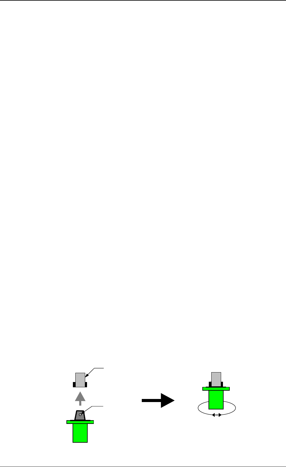
Nozzle Clamp Section
The clamp lever comes to the
position where it opens both in
front and rear.
Note the direction of the nozzle.
The groove for the clamp is
directed forward and backward.
Turn the special jig nozzle
slightly right and let and check
that the nozzle is clamped
securely by the clamp section.
Groove for Clamp