4OM-1011-002.pdf - 第283页
0305-001 Tg0860-PM-MM 5 - B

0305-001 Tg0860-PM-MM
Section 5
Touch Screen
5-A
This section explains the touch panel image adjustment, etc.

0305-001 Tg0860-PM-MM
5-B
0305-001 Tg0860-PM-MM
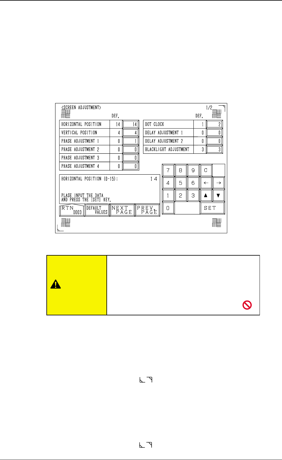
1. SCREEN ADJUSTMENT Display
•
The touch screen can be adjusted.
While the display for “Log In” type selection or the initial display is active,
lock the operation panel to be used for screen adjustment by pressing the
[PNL CHANGE] button. The operation lock LED illuminates. Then, press
the [RESET] and [STOP] buttons at the same time. The following display
appears on the screen.
Note: The locked operation mode cannot be canceled until the display for
“Log In” type selection or the initial display is closed.
HORIZONTAL POSITION
Set a parameter to adjust the insufficient width in raster and picture.
Enter “0” to “15” in the data box.
The standard value is “7”.
When the value is larger than this, the reproduced picture rolls to the right.
When smaller, the picture rolls to the left.
Adjust the frame corner marks ( located at the top right and bottom left
corners) such that the marks fit the screen corners properly.
VERTICAL POSITION
Set a parameter to adjust the insufficient height in raster and picture.
Enter “0” to “7” in the data box.
The standard value is “4”.
When the value is larger than this, the reproduced picture rolls upward.
When smaller, the picture rolls downward.
Adjust the frame corner marks ( located at the top right and bottom left
corners) such that the marks fit the screen corners properly.
5-1
1. SCREEN ADJUSTMENT Display
Fig. 4E1
Do not change the parameters unless necessary.
These parameters are factory-adjusted upon ship-
ment of the machine.
If correct parameters are not set, a key position,
etc., on the touch screen may
deviate from actually touched area.
CAUTION