4OM-1011-002.pdf - 第56页
0305-001 Tg0860-PM-MM 3. MANAGEMENT DA T A Display Menus are provided to manage operation rate, production rate, running condi- tion, etc., of the machine. When the [MANAGEMENT DA T A] key is pressed at the “SPECIAL SEL.…

0305-001 Tg0860-PM-MM
*5 [MANUAL AXIS OPERATION] Key
When this key is pressed, the “MANUAL AXIS OPERATION” display
appears on the screen, enabling the manual axis operation of each indi-
vidual devices.
Refer to “7. MANUAL AXIS OPERATION Display of Section 4 in Vol-
ume 1” for details.
*6 [MANUAL BYPASS] Key
When this key is pressed, the “MANUAL BYPASS” display appears on the
screen, enabling the manual bypass setting of a head or a component recog-
nition camera which is not in good shape or which should not be used.
The bypass setting can also be canceled manually.
*7 [TEACH OFFSET] Key
When this key is pressed, the “TEACH OFFSET” display appears on the
screen, enabling the teaching of various offset data.
After teaching operation, automatically calculated data is saved replacing
the previously saved offset data.
*8 [DEVICE TEST] Key
When this key is pressed, the “DEVICE TEST” display appears on the
screen.
The devices can be activated actually to check operations and functions
when new pattern program or component library data is created.
The [X/Y BEAM TEST], the [P.E.C. RECOG TEST], and the [COMPO-
NENT RECOG TEST] keys are provided.
*9 [DEVICE CHECK] Key
When this key is pressed, the “DEVICE CHECK” display appears on the
screen, enabling the check operation of various sensors’ input ports and the
read/write check operation of CPU boards 1, 2, and 3, the memory board,
and the recognition board.
*10[UNIT ADJUSTMENT] Key
When this key is pressed, the “UNIT ADJUSTMENT” display appears on
the screen, enabling the adjustment of each individual devices.
*11[HDD/FDD OPERATION] Key
When this key is pressed, the “HDD/FDD OPERATION” display appears
on the screen, enabling the load or save operation of the placement data,
using floppy disks.
3-4
2. SPECIAL SEL. Display
0305-001 Tg0860-PM-MM
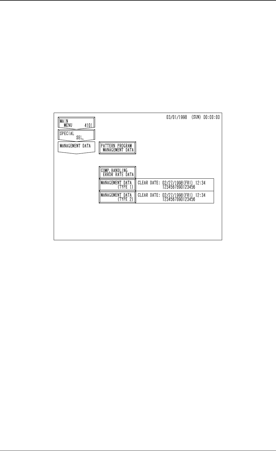
3. MANAGEMENT DATA Display
Menus are provided to manage operation rate, production rate, running condi-
tion, etc., of the machine.
When the [MANAGEMENT DATA] key is pressed at the “SPECIAL SEL.”
display, the following display appears on the screen.
This display can also be opened from the “AUTO OPN. SUB-MENU”
display.
[PATTERN PROGRAM MANAGEMENT DATA] Key
Management data is summed up for each pattern program data.
As this information is collected independently for each pattern program,
each bit of information and time data of a pattern program is summed up
only when the pattern program is active as the current program.
Thus, when a particular pattern program is used periodically during a span
of time, data is collected only during the times which that program is ac-
tive. This management data makes it possible to track each program's per-
formance and machine productivity individually.
This management data gives individual information of each pattern pro-
gram data enabling the management of the selected model production.
[COMP. HANDLING ERROR RATE DATA] Key
This key is used to check pick-up rate calculated for each feeder or nozzle
and based on each pick-up rate specified in the auto operation set-up data.
3. MANAGEMENT DATA Display
3-5
Fig. 4C4
0305-001 Tg0860-PM-MM
[MANAGEMENT DATA (TYPE 1)] and [MANAGEMENT DATA (TYPE
2)] Keys
Information data of the whole machine performance is collected and dis-
played.
A group of items related to machine maintenance are mainly summed up.
The number of finished P.C.B.’s is counted up not limited to the current
pattern program data but including all implemented pattern programs. That
is, the cumulative total of P.C.B.’s finished according to several pattern
programs can be regarded as the completed amount of P.C.B.’s.
There are two types (TYPE 1 and TYPE 2) of management data whose
only difference is the date and time which they are cleared (this is based on
individual needs for management data tracking. The possibility is using
one for weekly tracking and the other for monthly tracking).
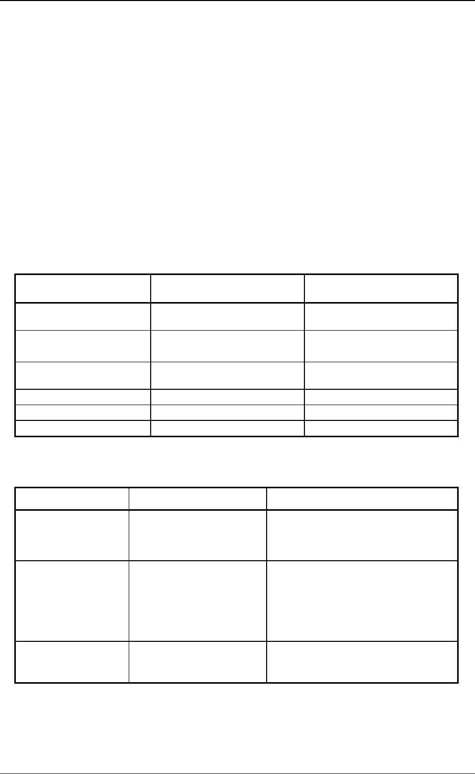
Difference between Pattern Program Management Data and Man-
agement Data
Deletion of Information Data
Note: Head and nozzle management data can be deleted for each head and
nozzle. Clear date is also updated for each nozzle.
(All data is cleared at one time.)
3. MANAGEMENT DATA Display
Table 4C1
Item
Pattern Program
Management Data
Management Data
Pattern Program
Production History
○ ×
Machine Performance Data
○
(P.C.B. Process Time)
○
(No P.C.B. Process Time)
Handling Errors per Feeder
Location
○ ○
Head Management Data
× ○
Nozzle Management Data
× ○
Sub-System Error Counts
× ○
Item
How to delete
What is deleted
Pattern Program
Management Data
Press the [CLEAR PATTERN
PRGM. MGT. DATA] key.
Pattern Program Production History
Machine Performance Data
Handling Error per Feeder Location
(Clear date is updated after deletion.)
Management Data
Press the [CLEAR
MANAGEMENT DATA
(TYPE 1) or (TYPE 2)] key.
Machine Performance Data
Handling Errors per Feeder Location
Head Management Data
Nozzle Management Data
Sub-System Error Counts
(Clear date is updated after deletion.)
Component Handling
Error Rate Data
(Various Data)
Change each set value at
the “AUTO OPERATION
SET-UP” display.
Individual Pick-Up Rate
(Saved or Current Data)
Table 4C2
3-6