4OM-1011-002.pdf - 第171页
0305-001 Tg0860-PM-MM 6.12.2 FEEDER (B) OFFSET • • • • • ECC. LOCA TE OFFSET Display (Option) • This display allows the teaching operation on the feeder (B) offset and ec- centric pick-up location of the multi-layer tray…
0305-001 Tg0860-PM-MM
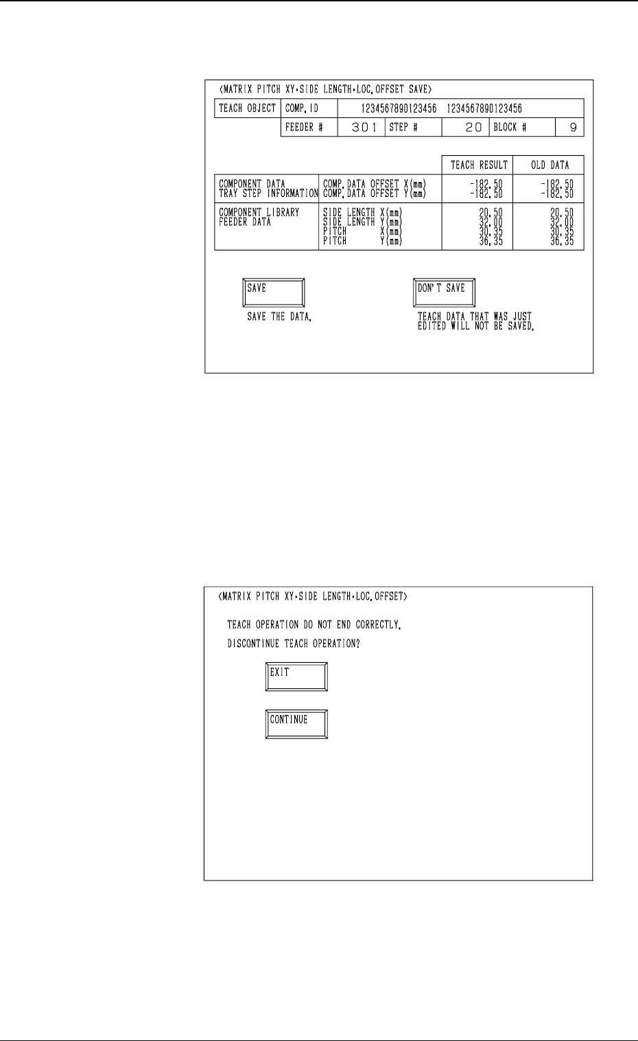
(12) When the teaching operation on the three items is com-
pleted, the following display appears on the screen.
(13) Check the data and determine whether it should be saved
or not.
• When the [SAVE] key is selected, the data is saved
and the display (Fig. 4C206) appears on the screen.
• When the [DON’T SAVE] key is selected, the data is
not saved and the display (Fig. 4C206) appears on the
screen.
• When the teaching operation on the three items is not com-
pleted and the [RTN] key is pressed, the following display
appears on the screen.
Enabling the operator to decide whether or not the teaching
operation should be interrupted.
• When the [EXIT] key is selected, the results of the teach-
ing operation are not reflected and the display (Fig. 4C206)
appears on the screen.
• When the [CONTINUE] key is selected, the display (Fig.
4C219) appears on the screen, enabling the operator to con-
tinue the teaching operation.
3-119
6.12 PICK-UP LOCATION (TRAY) Display (Option)
Fig. 4C229
Fig. 4C230
0305-001 Tg0860-PM-MM
6.12.2 FEEDER (B) OFFSET
••
••
•
ECC. LOCATE OFFSET
Display (Option)
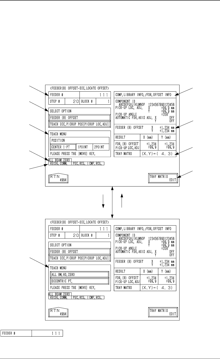
• This display allows the teaching operation on the feeder (B) offset and ec-
centric pick-up location of the multi-layer tray feeder (option).
When the [FEEDER (B) OFFSET ECC. LOCATE POSITION] key is pressed
at the “PICK-UP LOCATION (TRAY)” display, the following display appears
on the screen.
*1 “FEEDER #”
Shown is the feeder No. which was specified at the display
(Fig. 4C206).
[TEACH ECC. PICKUP POS
[PICKUP LOC. ADJ]] Key
[FEEDER (B) OFFSET] Key
*1
*2
*3
*9
*10
*4
*5
*6
*7
*8
3-120
6.12 PICK-UP LOCATION (TRAY) Display (Option)
Fig. 4C231
Fig. 4C232
Fig. 4C233
0305-001 Tg0860-PM-MM
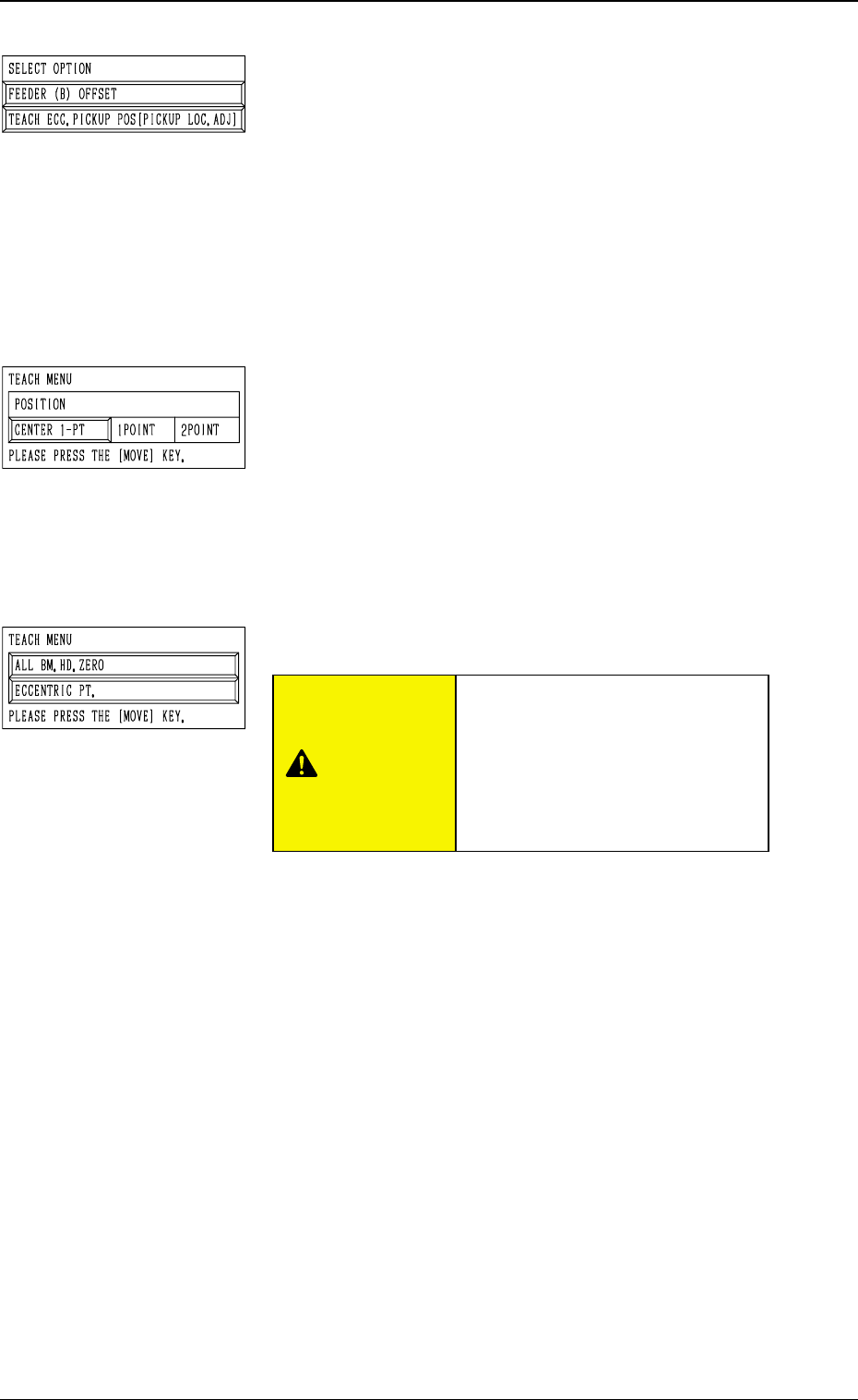
*2 “SELECT OPTION”
[FEEDER (B) OFFSET] Key
When the display (Fig. 4C232) is active and this key is
pressed, the display (Fig. 4C231) appears on the screen.
Use this function to perform the teaching operation on
the component center position.
[TEACH ECC. PICKUP POS [PICKUP LOC. ADJ]] Key
When the display (Fig. 4C231) is active and this key is
pressed, the display (Fig. 4C232) appears on the screen.
Use this function when a component has a groove, a
protrusion, etc., and cannot be picked up at the center
without any hindrance.
*3 “TEACH MENU”
“FEEDER (B) OFFSET (X, Y)” is modified additionally.
[CENTER 1-PT.] Key
When this key is pressed, the X/Y beam moves to the
center of the component.
“1POINT” and “2POINT”
These labels are used to align the component with two
diagonally-located points.
When the maximum outside dimensions of the compo-
nent exceeds “10 × 10 mm”, use these keys.
*4 “TEACH MENU”
[ALL BM. HD. ZERO] Key
This key is used to zero both Beams A and B.
When this key is selected and the [MOVE] button is
pressed, the zeroing operation starts.
[ECCENTRIC PT.] Key
When this key is selected and the [MOVE] button is
pressed, the P.E.C. recognition camera moves to the des-
ignated pick-up location correction position based on the
component center position (Position of “Design Position
+ Feeder (A) Offset + Feeder (B) Offset”) of the perti-
nent feeder, making it possible to capture the image.
Under this condition, shift to the trackball operation and
perform the manual alignment operation.
Note: It is necessary to correctly teach the component
center position before the eccentric position is
adjusted.
3-121
6.12 PICK-UP LOCATION (TRAY) Display (Option)
Fig. 4C234
Fig. 4C235
Fig. 4C236
CAUTION
“PICK-UP LOCATION ADJUST-
MENT X, Y” in the component li-
brary data is modified additionally.
Incorrect teaching operation will
cause the pick-up rate to deterio-
rate.