4OM-1011-002.pdf - 第284页
0305-001 Tg0860-PM-MM 1. SCREEN ADJUSTMENT Display • The touch screen can be adjusted. While the display for “Log In” type selection or the initial display is active, lock the operation panel to be used for screen adjust…

0305-001 Tg0860-PM-MM
5-B
0305-001 Tg0860-PM-MM
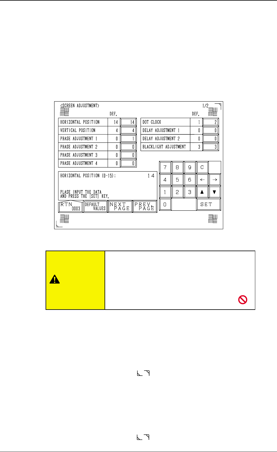
1. SCREEN ADJUSTMENT Display
•
The touch screen can be adjusted.
While the display for “Log In” type selection or the initial display is active,
lock the operation panel to be used for screen adjustment by pressing the
[PNL CHANGE] button. The operation lock LED illuminates. Then, press
the [RESET] and [STOP] buttons at the same time. The following display
appears on the screen.
Note: The locked operation mode cannot be canceled until the display for
“Log In” type selection or the initial display is closed.
HORIZONTAL POSITION
Set a parameter to adjust the insufficient width in raster and picture.
Enter “0” to “15” in the data box.
The standard value is “7”.
When the value is larger than this, the reproduced picture rolls to the right.
When smaller, the picture rolls to the left.
Adjust the frame corner marks ( located at the top right and bottom left
corners) such that the marks fit the screen corners properly.
VERTICAL POSITION
Set a parameter to adjust the insufficient height in raster and picture.
Enter “0” to “7” in the data box.
The standard value is “4”.
When the value is larger than this, the reproduced picture rolls upward.
When smaller, the picture rolls downward.
Adjust the frame corner marks ( located at the top right and bottom left
corners) such that the marks fit the screen corners properly.
5-1
1. SCREEN ADJUSTMENT Display
Fig. 4E1
Do not change the parameters unless necessary.
These parameters are factory-adjusted upon ship-
ment of the machine.
If correct parameters are not set, a key position,
etc., on the touch screen may
deviate from actually touched area.
CAUTION

0305-001 Tg0860-PM-MM
PHASE ADJUSTMENT 1
Set a parameter to change the phase of the sampling clock for better picture
quality.
Enter “0” or “1” in the data box.
The standard value is “0”.
PHASE ADJUSTMENT 2
Set a parameter to change the phase of the sampling clock for better picture
quality.
Enter “0” or “1” in the data box.
The standard value is “0”.
PHASE ADJUSTMENT 3
Set a parameter to change the phase of the sampling clock for better picture
quality.
Enter “0” or “1” in the data box.
The standard value is “0”.
PHASE ADJUSTMENT 4
Set a parameter to change the phase of the sampling clock for better picture
quality.
Enter “0” or “1” in the data box.
The standard value is “0”.
DOT CLOCK
Select the VC0 circuit (high frequency circuit) to reduce the difference in
the dot clock (image frequency = bit rate) which depends on the host com-
puter being used.
The standard value is “1”.
Change the parameters set in the “PHASE ADJUSTMENT 1”, “PHASE
ADJUSTMENT 2”, “PHASE ADJUSTMENT 3”, “PHASE ADJUST-
MENT 4” and “DOT CLOCK” data boxes such that the marks (
)
located at the four corners should not flicker and the color should not be
mottled or blurred.
DELAY ADJUSTMENT 1
Set a parameter to delay the sampling clock supplied to the LCD.
Enter “0” to “7” in the data box.
The standard value is “0”.
Note: Do not change the setting unless necessary. Otherwise, images on
the screen will appear in bad shape.
DELAY ADJUSTMENT 2
Set a parameter to delay the sampling clock supplied to the counter circuit.
Enter “0” to “7” in the data box.
The standard value is “0”.
Note: Do not change the setting unless necessary. Otherwise, images on
the screen will appear in bad shape.
BACKLIGHT ADJUSTMENT
Set a parameter to adjust the brightness of the back light.
“0” is the minimum value and “3” the maximum, representing the bright-
ness.
It takes a few minutes before the brightness of CFL (cold-cathode tube)
becomes stable after the illumination. When the brightness becomes stable,
adjust the brightness of the back light.
The standard value is “3”.
5-2
1. SCREEN ADJUSTMENT Display