4OM-1011-002.pdf - 第144页
0305-001 Tg0860-PM-MM 3-93 When the [MASTER] key is pressed at the "NOZZLE STOCKER OFFSET" display (Fig. 4C162), the display shown in Fig. 4C163 appears. Note: When the [LOCAL] key is pressed, the same display …
0305-001 Tg0860-PM-MM
6.8.5 Nozzle Stocker Offset
Notes: (a) A special jig (option) is required for accurate teaching operations.
Set the jig to the stocker address position to be taught in advance.
(b) If the offset data is not taught accurately, the nozzle change opera-
tion cannot be performed correctly.
• Set the jig or a nozzle on the nozzle stocker and perform the offset teaching
operation for the feeder through manual alignment operation.
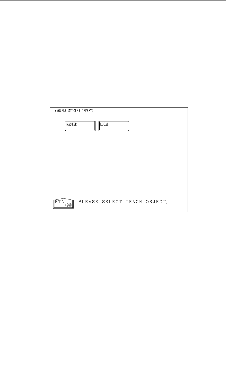
When the [NOZZLE STOCKER OFFSET] key is pressed at the “UNIT
MANUAL ALIGNMENT TEACH” display, the following display appears on
the screen.
[MASTER]
When this key is pressed, the display appears where the nozzle stoker entire
deviation is taught.
[LOCAL]
When this key is pressed, the display appears where the nozzle stokers 1 to
10 are taught individually.
3-92
6.8 UNIT MANUAL ALIGNMENT TEACH Display
Fig. 4C162
0305-001 Tg0860-PM-MM
3-93
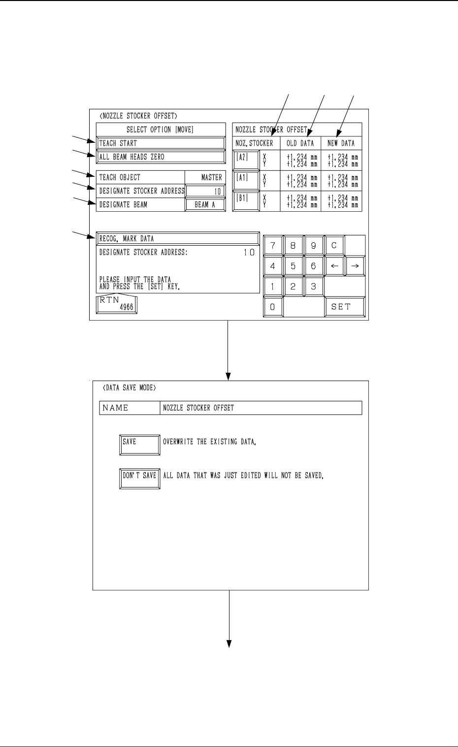
When the [MASTER] key is pressed at the "NOZZLE STOCKER OFFSET" display
(Fig. 4C162), the display shown in Fig. 4C163 appears.
Note: When the [LOCAL] key is pressed, the same display appears.
6.8 UNIT MANUAL ALIGNMENT TEACH Display
Fig. 4C163
Fig. 4C164
[RTN] Key
[DON’T SAVE] Key[SAVE] Key
"NOZZLE STOCKER OFFSET" display (Fig. 4C162)
*9
*1
*8
*5
*4
*3
*2
*6
*7

0305-001 Tg0860-PM-MM
*1 NOZ. STOCKER [A1] and [B1] Keys
Select one of the keys to specify the nozzle stocker unit for which the manual
alignment and teaching operations must be performed.
*2 TEACH OBJECT [MASTER] or [LOCAL]
This shows “TEACH OBJECT” selected at the display in Fig 4C162.
*3 DESIGNATE STOCKER ADDRESS
When “TEACH OBJECT” is the “MASTER”:
The address (1 to 10) for the nozzle stocker is designated as the refer-
ence position for all teaching.
When “TEACH OBJECT” is the “LOCAL”:
This designates the stocker address (1 to 10) for the nozzle to be taught.
*4 DESIGNATE BEAM
Designate the X/Y beam on which the teaching operation must be per-
formed.
*5 [RECOG MARK DATA EDIT] Key
When this key is pressed, the “RECOG. MARK DATA EDIT” display (Fig.
4C168) appears on the screen, enabling the designation of a template shape
to appear on the recognition monitor.
The template shape can be specified for manual alignment with the align-
ment point.
Refer to “6.8.8 Editing of Recognition Mark Data” for details.
*6 [ALL BEAM HEADS ZERO] Key
Both Beams A and B are zeroed.
When this key is selected and the [MOVE] button is pressed, the zeroing
operation starts.
*7 [TEACH START] Key
When this key is selected and the [MOVE] button is pressed, the P.E.C.
recognition camera moves to the specified nozzle stocker position.
The teaching point appears on the recognition monitor. Perform the manual
alignment using the track ball.
Refer to "3.6.8.9 Teaching Operation with Track Ball" for details.
*8 OLD DATA
Displayed are the values before each nozzle stocker offset data is taught.
*9 NEW DATA
Displayed are the values after each nozzle stocker offset data is taught.
Before the teaching operation is performed, the same values as *7 are dis-
played.
3-94
6.8 UNIT MANUAL ALIGNMENT TEACH Display