4OM-1011-002.pdf - 第163页
0305-001 Tg0860-PM-MM The following three methods are prepared for the component data offset teaching. Operation Procedure (Movement of Data Position) (1) Select the [DA T A POS. MOVE] key of “MODE”. (2) Select the [CENT…
0305-001 Tg0860-PM-MM
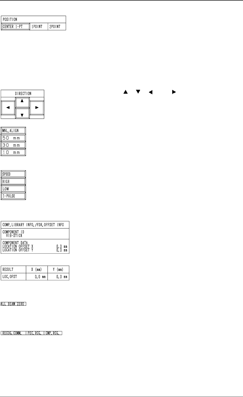
*3 “POSITION”
[CENTER 1-PT] Key
When this key is pressed, the X/Y beam moves to the
center of the component.
“1POINT” and “2POINT”
These labels are used to align the component with two
diagonally-located points.
When the maximum outside dimensions of the compo-
nent is “10 × 10 mm”, use these keys.
*4 “DIRECTION” [ ], [ ], [ ], and [ ] Keys
Use these keys to specify the direction in which the X/Y
beam is manually aligned.
*5 [MNL. ALIGN], [10 mm], [30 mm], and [50 mm] Keys
Use these keys to select the distance by which the X/Y
beam is manually aligned.
When the [MNL. ALIGN] key is pressed, the [SPEED]
and the related keys appear in place.
*6 [SPEED], [HIGH], [LOW], and [1 PULSE] Keys
Use these keys to specify the speed at which the X/Y beam
is manually and smoothly aligned (smooth manual align-
ment).
When the [SPEED] key is pressed, the [MNL. ALIGN]
and the related keys appear in place.
*7 “COMP. LIBRARY INFO./FDR. OFFSET INFO”
Displayed are the component library data and the compo-
nent data offset of the selected feeder No.
*8 “RESULT X (mm), Y (mm)”
When the teaching operation is completed, the results are
displayed.
*9 “ALL BEAM ZERO”
When all beams are zeroed completely, the background turns
green. Otherwise, the background has no color.
*10 “RECOG. COMM.”
When “DISABLE” is set in the “P.E.C.” and “COMPO
NENT RECOGNITION” data boxes at the “TEST
MODE” display, the background color of “P.E.C. RECOG.”
and “COMP. RECOG.” becomes light red. (No background
color in normal cases)
3-111
6.11 COMPONENT DATA (VIB. STICK) OFFSET Display
Fig. 4C198
Fig. 4C199
Fig. 4C200
Fig. 4C201
Fig. 4C202
Fig. 4C203
Fig. 4C204
Fig. 4C205

0305-001 Tg0860-PM-MM
The following three methods are prepared for the component data offset
teaching.
Operation Procedure (Movement of Data Position)
(1) Select the [DATA POS. MOVE] key of “MODE”.
(2) Select the [CENTER 1-PT] key (the [1POINT] key in the case of diago-
nal 2-point alignment) and press the [MOVE] button.
The X/Y beam moves to the position where the parameters set in the “X
(mm)” and “Y (mm)” data fields of the label “OFFSET” in the component
data are referred to.
(3) In the case of diagonal 2-point alignment, select the [2POINT] key and
press the [MOVE] button.
Manual Alignment Operation Procedure (Trackball Operation)
(1) Select the [MANUAL ALIGNMENT] key of “MODE”.
(2) Select the [CENTER 1-PT] key (the [1POINT] key in the case of diago-
nal 2-point alignment) and press the [MOVE] button.
(3) Manipulate the trackball to perform the manual alignment.
Refer to “6.8.9 Teaching Operation with Trackball” for details.
(4) In the case of diagonal 2-point alignment, select the [2POINT] key and
press the [MOVE] button. Then, manipulate the trackball to perform the
manual alignment.
Operation Procedure (Smooth Manual Alignment)
(1) Select either the [ ], the [ ], the [ ], or the [ ] key of “DIRECTION”.
(2) Select the speed by selecting one of the keys under “SPEED”.
(3) The X/Y beam moves in the specified direction at the selected speed
while the [MOVE] button is being pressed.
It stops when the [MOVE] button is released.
Operation Procedure (Inching Movement)
(1) Select either the [ ], the [ ], the [ ], or the [ ] key of “DIRECTION”.
(2) Select either the [50 mm], the [30 mm], or the [10 mm] key of “MNL.
ALIGN”.
(3) When the [MOVE] button is pressed, the X/Y beam moves in the speci-
fied direction as far as the specified distance (inching distance).
3-112
6.11 COMPONENT DATA (VIB. STICK) OFFSET Display
0305-001 Tg0860-PM-MM
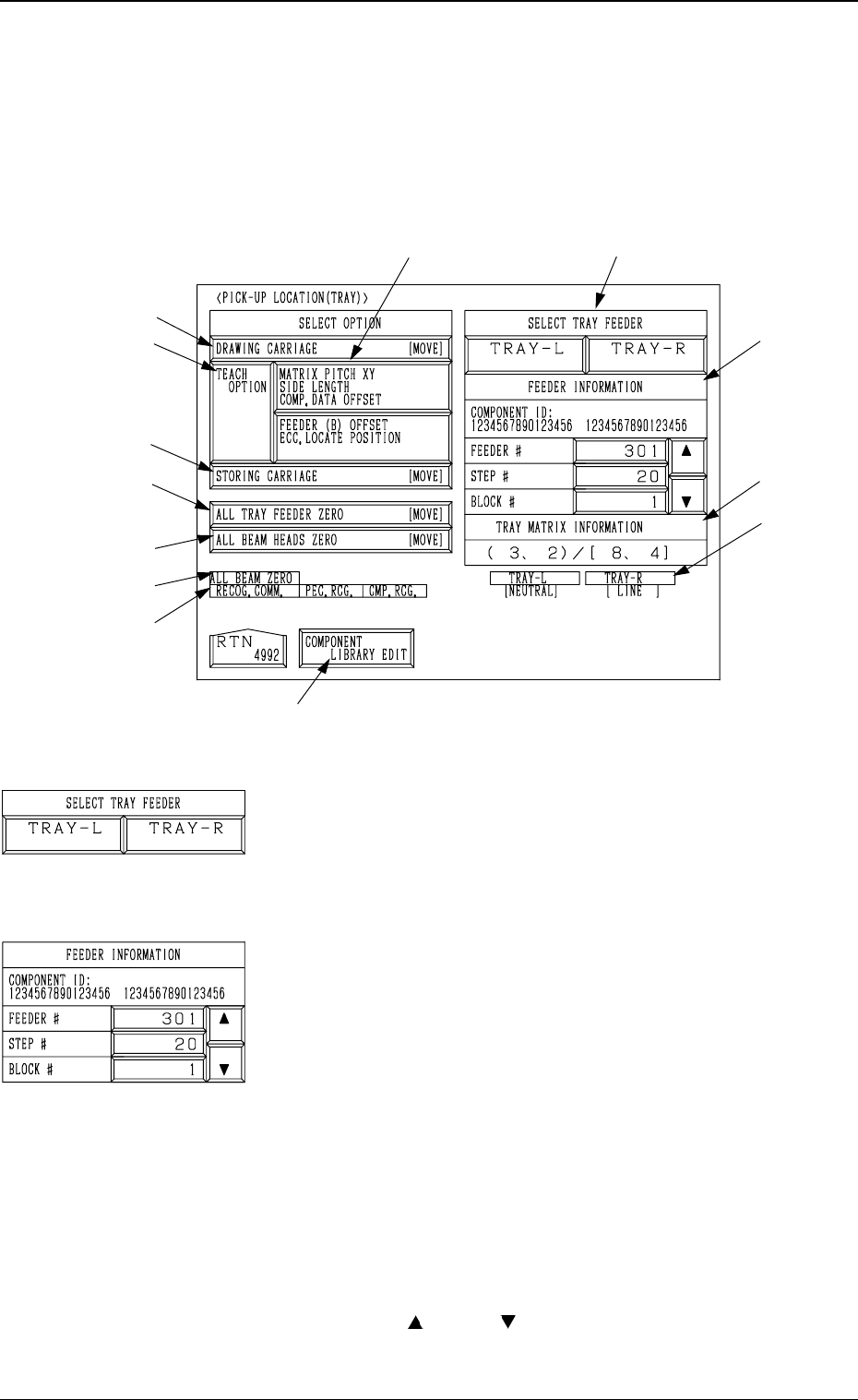
6.12 PICK-UP LOCATION (TRAY) Display (Option)
• This display allows the teaching operations on the pick-up position offset of
the component to be supplied from the multi-layer tray feeder (option).
When the [TRAY] key is pressed at the “PICK-UP LOCATION” display, the
following display appears on the screen.
*1 “SELECT TRAY FEEDER” [TRAY-L] and [TRAY-R]
Keys
Select the multi-layer tray feeder where the components to
be taught are set.
Note: The tray feeder not registered in the component of
the current pattern program cannot be selected.
*2 “FEEDER INFORMATION”
Select the component (FDR NO.) to be taught.
Note: No selection can be made with the pallet being
drawn out.
*a “COMPONENT ID”
Displayed is the component ID related to the
specified feeder No.
*b “FEEDER #”
Displayed is the multi-layer tray feeder which
is selected by “SELECT TRAY FEEDER” in
*1 and has the smallest feeder No. among the
registered ones.
Only the feeder No. registered in the compo-
nent data of the current
pattern program is dis-
played and scrolled up or down by pressing the
[ ] or the [ ] key on the right side.
Note: When only one feeder No. is regis-
tered, it cannot be scrolled up or down.
*5
*7
*6
*8
*2
*9
*3
*4
*10
*11
*7
*1
*12
6.12 PICK-UP LOCATION (TRAY) Display (Option)
Fig. 4C206
3-113
Fig. 4C207
Fig. 4C208