4OM-1011-002.pdf - 第124页
0305-001 Tg0860-PM-MM *1 [ALL BEAM] Key The machine performs the teaching operation of the head position of fset for simultaneous image capture operations at both Beams A and B. When this key is selected and the [MOVE] b…
0305-001 Tg0860-PM-MM
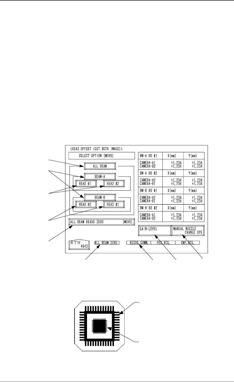
6.6 HEAD OFFSET (GET BOTH IMAGE) Display
• This display enables you to teach the head position offset for the simulta-
neous image capture operation, indicating where the head rotational center
of the subordinate head is located in comparison with the center of the con-
fronting camera when the component recognition function (simultaneous
recognition function) is implemented with components being picked up by
the right and left heads.
Calculate the offset value by recognizing the pattern of the printing to the
teaching jig component plate (component recognition offset jig) which picked
up with the nozzle with the component recognition camera.
Note: Follow the teaching procedures in the specified order. Otherwise, some
trouble (such as inaccurate component placement, frequent mechani-
cal errors, etc.) will arise.
When the [HEAD OFFSET (GET BOTH IMAGE)] key is pressed at the
“TEACH OFFSET” display, the following display appears on the screen.
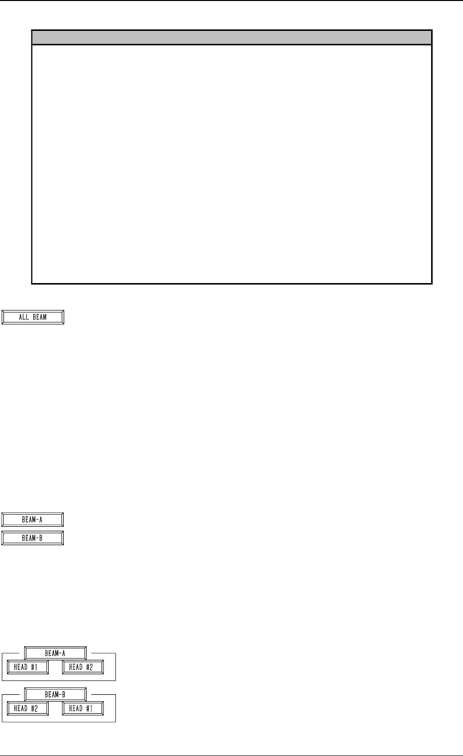
Teaching Plate (Component Recognition Offset Jig: JG-0085)
(Standard Accessory Part)
Note: Handle this fragile jig very carefully.
• Two types of patterns are printed through vapor deposition on the glass for
positional calculation.
*7
*8
*2
*1
*3
*5
*6
*4
*3
3-72
6.6 HEAD OFFSET (GET BOTH IMAGE) Display
Fig. 4C128
Pattern to be captured by the
component recognition camera
Pattern to be captured by the
P.E.C. recognition camera
Fig. 4C129
0305-001 Tg0860-PM-MM
*1 [ALL BEAM] Key
The machine performs the teaching operation of the head
position offset for simultaneous image capture operations
at both Beams A and B.
When this key is selected and the [MOVE] button is pressed,
the machine starts the teaching operation.
Note: Before performing the teaching operations, zero
both beams.
It is calculated through the procedures similar to the teach-
ing operation of the head rotational center offset data where
the head rotational center is located when viewed from the
camera center in comparison with the camera positioned as
the subordinate head during simultaneous recognition for
each individual heads.
*2 [BEAM-A] and [BEAM-B] Keys
The machine performs the teaching operation of the head
position offset for simultaneous image capture operations
at Beam A or B.
When the [BEAM-A] or the [BEAM-B] key is selected and
the [MOVE] button is pressed, the machine starts the teach-
ing operation.
Note: Before performing the teaching operations, zero
both beams.
*3 [HEAD #1] and [HEAD #2] Keys in “BEAM-A” Group
Box and [HEAD #2] and [HEAD #1] Keys in “BEAM-B”
Group Box
When one of the above-described keys is selected and the
[MOVE] button is pressed, the machine starts teaching the
offset data related to the selected head #.
Note: Before performing the teaching operations, zero
both beams.
3-73
6.6 HEAD OFFSET (GET BOTH IMAGE) Display
Reference
Subordinate Head:
When two steps are paired through the simultaneous pick-up or the pick-up priority function
designated in the placement data, this head handles the component related to the step No. larger
than the other. On the other hand, the head which handles the component related to the smaller
step No. is called "Guide Head".
The simultaneous recognition is automatically prohibited and images are captured individually
when;
• components which require BGA lighting are picked up.
• a value other than "0" (zero) is set (designation of eccentric pick-up) in the "X" and "Y" data
boxes of the label "PICK-UP LOCATION CORRECTION" at the "CMPNT LIBRARY"
display.
• the visual field of the confronting camera cannot cover the components picked up by the right
and left heads.
In these cases, the beams must be moved such that the rotational centers of the heads are located
at the camera centers before the images are captured.
Compared with this, in the case of the simultaneous recognition, the guide head (for the smaller
step) moves normally but the subordinate head faces the other one at the position where the head
rotational center does not match the camera center due to the relation between the head-to-head
and camera-to-camera pitches. Therefore, this offset data is required for recognition processing
and correction calculation.
Fig. 4C130
Fig. 4C131
Fig. 4C132

0305-001 Tg0860-PM-MM
*4 [ALL BEAM HEADS ZERO [MOVE]] Key
Both Beams A and B are zeroed.
When this key is selected and the [MOVE] button is pressed,
the zeroing operation starts.
*5 [GAIN・LEVEL] Key
When this key is pressed, the “GAIN・LEVEL” display (Fig.
4C70) appears on the screen.
These parameters are used to set amplifications at which
the image signals of the image taken by the component rec-
ognition camera is converted into the picture information
representing brightness.
Parameters are set as the offset values for camera reference
gain and level.
Normal Fixed Value: ± 0
• When “ENABLE” is set in the “DESIGNATE” data box,
be sure to set parameters in the “GAIN” and “LEVEL”
data boxes.
The set parameters are used for P.E.C. recognition.
When “DISABLE” is set in the data box, the standard
parameters are set in the “GAIN” and “LEVEL” data
boxes.
• The lower the gain is, the bigger the contrast becomes.
• The lower the level is, the brighter the whole view be-
comes.
Note: Teaching operations are performed through com-
ponent recognition.
Incorrect gain and level parameters lead to the ad-
verse result of teaching operations, causing some
trouble.
*6 [MANUAL NOZZLE CHANGE OPE] Key
When this key is pressed, the “MANUAL NOZZLE
CHANGE OPERATION” display (Fig. 4C85) appears on
the screen.
Designate the head and the nozzle and attach either “MF01”-
, “MF02”- or “MA06”-type nozzle.
Refer to “9. Manual Nozzle Change Operation of Section
4 in Volume 1” for details.
*7 RECOG. COMM.
When “DISABLE” is set in the “P.E.C.” and “COMPO-
NENT RECOGNITION” data boxes at the “TEST MODE”
display, the background color of “P.E.C. RECOG.” and
“COMP. RECOG.” becomes light red. (No background
color in normal cases)
In this case, the recognition processing is not made even if
the teaching operations are performed. Therefore, the re-
sults of various teaching operations are not reflected on the
offset data.
*8 ALL BEAM ZERO
When all beams are zeroed completely, the background
color turns green. Otherwise, the background has no color.
3-74
6.6 HEAD OFFSET (GET BOTH IMAGE) Display
Fig. 4C133
Fig. 4C134
Fig. 4C135
Fig. 4C136
Fig. 4C137