00195779-0102_UM_D4_SR605_EN.pdf - 第100页
3 Technical data for the machine User manual SIPLACE D4 3.6 Gantry system From software version SR.605.xx 07/2008 EN Edition 100 3.6 Gantry system 3.6.1 Position of the gantries 3 Fig. 3.6 - 1 Position of the gantries (1…

User manual SIPLACE D4 3 Technical data for the machine
From software version SR.605.xx 07/2008 EN Edition 3.5 Placement head
99
3.5.1.3 Operation with a vacuum pump
The 12-segment Collect&Place head can be converted for operation with a vacuum pump for
more efficient vacuum generation (see Section 6.12
, page 245).
Programmed power stage
1
2
3
4
5
Programmed set-down force [N]
2.4 ± 0.5
2.4 ± 0.5
3 + 1
4 + 1
5 + 1
Nozzle types 9xx 9xx 9xx
X/Y accuracy
d
± 50 μm/3σ, ± 67 μm/4σ ± 50 μm/3σ, ± 67 μm/4σ ± 50 µm/3σ, ± 67 µm/4σ
Angular accuracy ± 0.53°/3σ, ± 0.71°/4σ ± 0.53°/3σ, ± 0.71°/4σ ± 0.53°/3σ, ± 0.71°/4σ
Component range 98% 98.5% 96%
Component camera type 28 29 38
Illumination levels 5 5 5
Possible illumination level
setting
256
5
256
5
256
5
a) Please note that the component range that can be placed is also affected by the pad geometry, the cus-
tomer-specific standards and the packaging tolerances.
b) With 0201 package
c) With 01005 package
d) The accuracy value was measured using the vendor-neutral IPC standard
3 Technical data for the machine User manual SIPLACE D4
3.6 Gantry system From software version SR.605.xx 07/2008 EN Edition
100
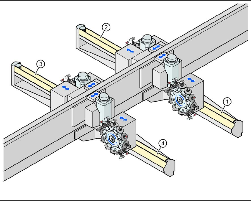
3.6 Gantry system
3.6.1 Position of the gantries
3
Fig. 3.6 - 1 Position of the gantries
(1) Gantry 1
(2) Gantry 2
(3) Gantry 3
(4) Gantry 4
The gantry system consists of two functional groups
–X axis and
–Y axis
Placement area 2
Placement area 1

User manual SIPLACE D4 3 Technical data for the machine
From software version SR.605.xx 07/2008 EN Edition 3.6 Gantry system
101
3.6.2 Structure of the X axis
3
Fig. 3.6 - 2 Structure of the X axis
The X axis essentially consists of the following main modules:
– Gantry arm (1)
– Head mount (2)
– Linear measuring system (3)
– X axis guide system (4)
– X axis three-phase AC servomotor (5)
The head mount holds the following components
– Sub-gantry camera (camera for the PCB vision module)
– Head board
– Measuring head for the X axis measuring system
– Collect&Place head