00195779-0102_UM_D4_SR605_EN.pdf - 第178页
4 Setting up and commissioning User manual SIPLACE D4 4.3 Setting up the machine From software version SR.605.xx 07/2008 EN Edition 178 4.3.9 Making final adjustment s to the machine → Place the machine's spirit lev…
User manual SIPLACE D4 4 Setting up and commissioning
From software version SR.605.xx 07/2008 EN Edition 4.3 Setting up the machine
177
4.3.8.3 Aligning the machine with respect to the line
→ Position the machine on the free location on the line using the fork-lift.
WARNING 4
Lower the machine slowly. A second person should look underneath to ensure that all the
machine foot touch the floor at the same time. If the machine feet on one side hit the ground
hard, the fixings may be damaged.
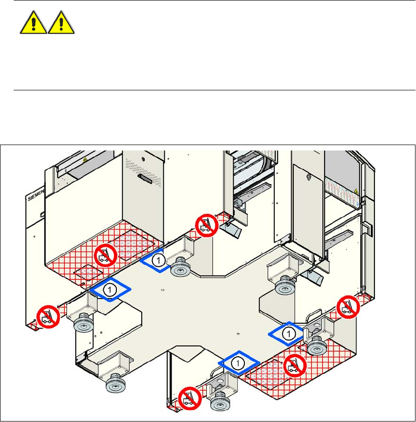
4.3.8.4 Aligning the machine with the air cushion transport system
4
Fig. 4.3 - 8 Contact positions for the air cushion transport system
(1) Contact surfaces for the air cushion transport system
→ Place the four air cushions of the air cushion transport system beneath the machine frame.
→ Raise the machine and align it with respect to the line.
→ Check the distance from the PCB conveyor system of the adjacent machine. It should be be-
tween 1 mm and 3 mm.
→ Lower the machine.

4 Setting up and commissioning User manual SIPLACE D4
4.3 Setting up the machine From software version SR.605.xx 07/2008 EN Edition
178
4.3.9 Making final adjustments to the machine
→ Place the machine's spirit level on the panels of the PCB conveyor in placement area 1 in
both the X and the Y directions. The PCB conveyor width is preset:
Single conveyor 210 mm
Dual conveyor, track 1 100 mm
Dual conveyor, track 2 210 mm 4
PLEASE NOTE: 4
On the dual conveyor, place the spirit level only on the outer panels of the machine for ad-
justing in the X direction.
→ Measure the distance between the top edge of the PCB conveyor belt and the floor. This dis-
tance should be 800 mm, 900 mm, 930 mm or 950 mm.
→ Use the size SW65 single-head wrench to adjust the outer machine feet (item 1 in Fig.
4.3 - 2
, page 168) so that the label on the machine spirit level does not deviate from the zero
point for the required PCB conveyor height.
→ Check the required PCB conveyor height.
→ Once the machine is aligned, tighten the lock nuts on the outer machine feet.
→ Unscrew the middle machine feet (item 3 in Fig. 4.3 - 2
, page 168) until they are seated firmly
on the ground.
→ Make sure that you do not unscrew the middle machine feet so far that the machine is no lon-
ger adjusted.
→ Lock the middle machine feet in position.
→ Use the spirit level to ensure that the machine is precisely aligned.
4.3.10 Removing the shipping braces
Remove all the shipping braces from the gantry axes.

User manual SIPLACE D4 4 Setting up and commissioning
From software version SR.605.xx 07/2008 EN Edition 4.3 Setting up the machine
179
4.3.11 Removing the corrosion protection from the guide rails
The machines were given a corrosion protection treatment before they were delivered.
CAUTION 4
– You should therefore remove the corrosion protection from all the axes and bearings when
you traverse the machine axes for the first time during commissioning.
– Grease all the axes and bearings with the grease described in the maintenance instructions.
If the corrosion protection agent is mixed with the bearing grease on the axes this can greatly re-
duce the service life of the bearings and guide rails.
CAUTION 4
Do not allow any alcohol to enter the guide carriages when you clean the guide rails and scale
rods. Alcohol will damage the bearing grease in the guide carriages.
4
4