00195779-0102_UM_D4_SR605_EN.pdf - 第220页
5 Tasks for the operating personnel User manual SIPLACE D4 5.10 Docking the component trolley in or out From software version SR.605.xx 07/2008 EN Edition 220 → Press the star t button to start the machine. → Push the sl…
User manual SIPLACE D4 5 Tasks for the operating personnel
From software version SR.605.xx 07/2008 EN Edition 5.10 Docking the component trolley in or out
219
5.10.2 Docking in the component trolley
PLEASE NOTE 5
Shorten the component tapes on the front end of the S feeder modules to approximately 1 cm
before you dock in the component trolley.
CAUTION 5
Check that the placement head is outside the range of the component trolley.
→ Make sure that the left and right contact surfaces (item 7 in Fig. 5.10 - 1
, page 217) for the
component table bed is clean.
→ Check that the contact surfaces on the underside of the component table bed are clean.
→ CAREFULLY push the component trolley into the machine.
→ Plug the connecting cable of the component trolley into the socket (item 2 in Fig. 5.10 - 1
,
page 217
) on the machine.
→ Open the cover over the push-button used to raise and lower the component table bed (item
1 in Fig. 5.10 - 1
, page 217).
→ Turn the switch on the component table (item 4 in Fig. 5.10 - 1
, page 217) down.
→ Press the button until the component table bed has reached the upper final position.
→ Carefully push the component trolley into machine as far as the stop.
→ Check that the centering holes in the component table bed lie precisely over the centering
pins of the machine (item 8 in Fig. 5.10 - 1
, page 217).
WARNING DANGER OF CRUSHING 5
When lowering the component table bed, never reach into the gap between the feeders and
the used tape channel. 5
→ Press the button for lowering the component table bed (item 4 in Fig. 5.10 - 1
, page 217).
→ Ensure that the centering pins engage in the centering holes in the component table bed and
that the component table bed is fully lowered.
→ Close the cover over the push-button (item 1 in Fig. 5.10 - 1
, page 217).
→ Close the protective cover.
5 Tasks for the operating personnel User manual SIPLACE D4
5.10 Docking the component trolley in or out From software version SR.605.xx 07/2008 EN Edition
220
→ Press the start button to start the machine.
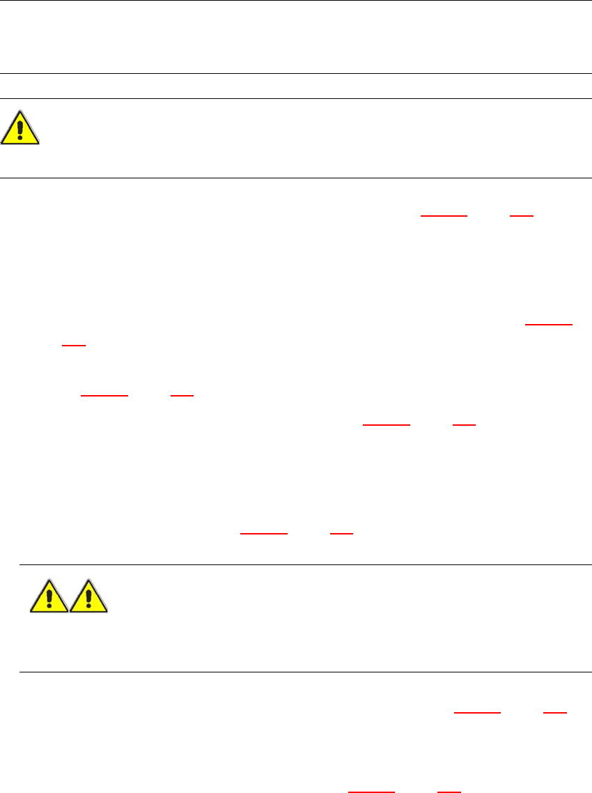
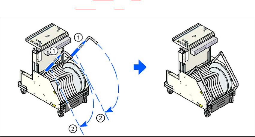
→ Push the sleeve (item 1 in Fig. 5.10 - 3
, page 220) up using both handles and swivel the han-
dle down (item 2 in Fig. 5.10 - 3
, page 220).
5
Fig. 5.10 - 3 Component trolley - swivel handles down
(1) Push sleeve up
(2) Fold handle down
User manual SIPLACE D4 6 Station extensions
From software version SR.605.xx 07/2008 EN Edition 6.1 Nozzle changer for the 12-nozzle Collect&Place head
221
6 Station extensions
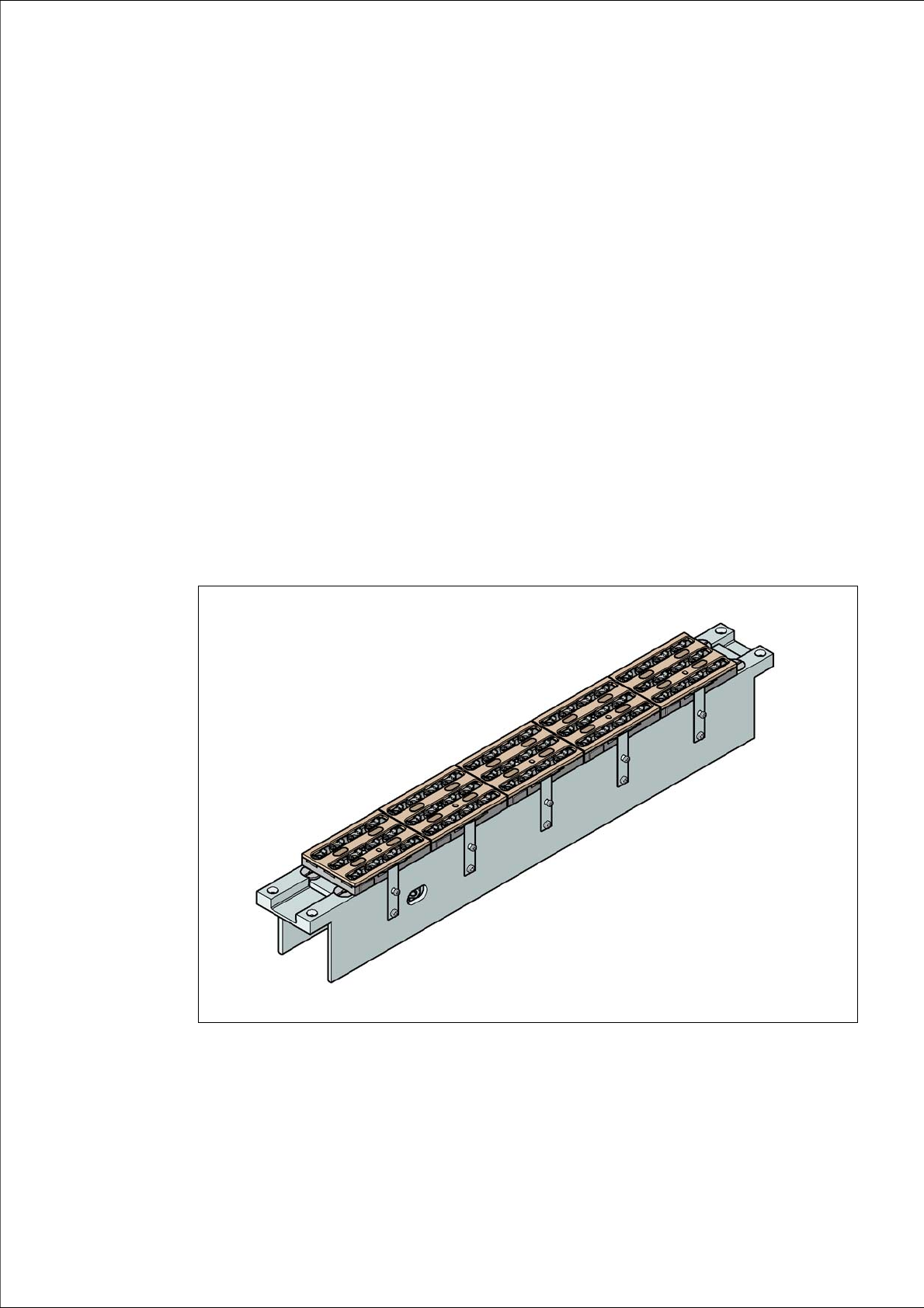
6.1 Nozzle changer for the 12-nozzle Collect&Place
head
Item no. 00119888-xx Nozzle changer, 12-segment C&P head, set
Item no. 00119161-xx Nozzle changer, 12-segment C&P head, 1x
Nozzle changers can greatly increase the flexibility of the placement heads for processing differ-
ent types of component. If the placement program requires a nozzle change, then the placement
head automatically returns the old nozzle to the nozzle holder and picks up the new nozzle. Noz-
zles that were separated out during the vacuum check can also be quickly changed.
It is significantly more exact and faster to pick up nozzles from a nozzle changer than would be
possible manually. When placing small components, it is essential to minimize the radial eccen-
tricity during nozzle rotation.
6
Fig. 6.1 - 1 Nozzle changer for the 12-segment Collect&Place head