00195779-0102_UM_D4_SR605_EN.pdf - 第206页
5 Tasks for the operating personnel User manual SIPLACE D4 5.5 Carrying out a walk-through inspection From software version SR.605.xx 07/2008 EN Edition 206 5.5.2 Splicing the t apes in good time PLEASE NOTE: S plice the…
User manual SIPLACE D4 5 Tasks for the operating personnel
From software version SR.605.xx 07/2008 EN Edition 5.5 Carrying out a walk-through inspection
205
5.5 Carrying out a walk-through inspection
5.5.1 Checking the S feeder modules
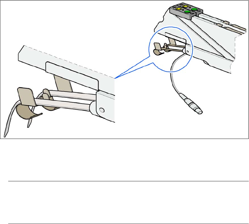
→ Make sure that the tape is correctly placed in the springs of the S feeder module.
5
Fig. 5.5 - 1 Placing the tape in the springs of the S feeder module
→ Check to see whether the tape foil removal container for the S feeder module is full.
If it is full, then pull out the foil and cut it off with scissors.
PLEASE NOTE
Tearing the foil instead of cutting it can lead to problems with the tape removal mechanism.
For this reason the 3 x 8 mm feeder modules are fitted with an integral cutter. This is in the
tape foil removal container at the end of the feeder module under the flaps. 5
→ Check to ensure that the pick-up window on combination feeder modules (24/32 mm) is the
right size for the component.
→ Check to see whether tape guides are inserted on combination feeder modules (24 mm /
32 mm).

5 Tasks for the operating personnel User manual SIPLACE D4
5.5 Carrying out a walk-through inspection From software version SR.605.xx 07/2008 EN Edition
206
5.5.2 Splicing the tapes in good time
PLEASE NOTE:
Splice the tapes early enough so that the feeder modules do not run out of components. Oth-
erwise you will experience prolonged down times.
However, do not splice the tapes too early because if you wind the end of the old tape onto
the new reel after splicing, the reel holding the new tape may become overfilled and the tape
will slip off the reel and become tangled up. This will again result in pick-up errors and pro-
longed down times. 5
5.5.3 Checking the PCB supports
→ Check the position of the magnetic PCB supports on the lifting table:
– Make sure that the PCB supports do not collide with components on the underside of the
PCBs.
– In addition, make sure that the PCB supports do not collide with the PCB conveyor panels.
– Only use PCB supports as described in Section 6.7
, page 239.
5.5.4 Inserting separating plates in the tape container
→ The separating plate has different edges and can be inserted into the tape container in two
ways. If spindles are used, the recesses for the spindles in the separating plate point upwards
(see item . 6 in Fig. 5.5 - 2
, page 207). If you do not use spindles, the rounded edge of the
separating plate points upwards (see item 5 in Fig. 5.5 - 2
, page 207).
→ Insert the separating plates as shown in Fig. 5.5 - 2
, page 207 and remember that the smallest
division of the tape container is a 2x division. This will help avoid placement errors.
→ Check that the separating plates engage in the same positions on the three guide rails. Oth-
erwise the separating plate will be offset or bent.
User manual SIPLACE D4 5 Tasks for the operating personnel
From software version SR.605.xx 07/2008 EN Edition 5.5 Carrying out a walk-through inspection
207
5
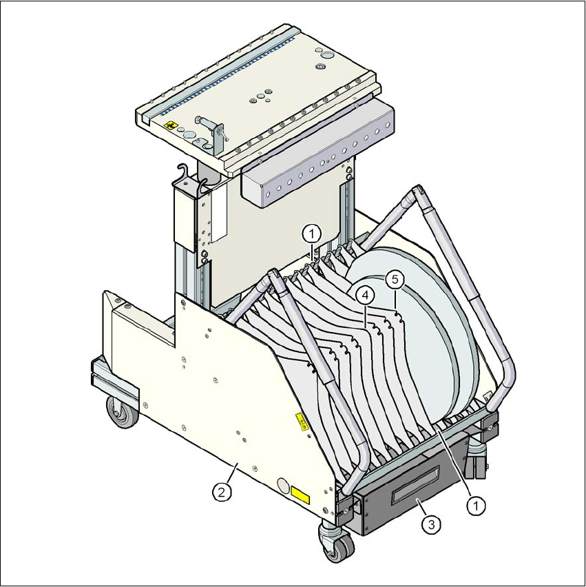
Fig. 5.5 - 2 Separating plates in the tape container
(1) Guide rail for the separating plates
(2) Tape container
(3) Waste tape container
(4) Position of the separating plate if no spindles are used
(5) Position of the separating plate if spindles are used