00195779-0102_UM_D4_SR605_EN.pdf - 第181页
User manual SIPLACE D4 4 Setting up and commissioning From software version SR.605.xx 07/2008 EN Edition 4.4 A dapting the component tro lley to the PCB conveyor height 181 4.4.3 Changing the component trolley height W A…

4 Setting up and commissioning User manual SIPLACE D4
4.4 Adapting the component trolley to the PCB conveyor height From software version SR.605.xx 07/2008 EN Edition
180
4.4 Adapting the component trolley to the PCB conveyor
height
The component trolley for the S feeder modules can be set to the following PCB conveyor heights
with just a few simple actions:
830 mm ± 15 mm Standard height
900 mm ± 15 mm Option
930 mm ± 15 mm Option
950 mm ± 15 mm SMEMA option 4
4.4.1 Warning instructions
WARNING 4
Only SIPLACE engineers or qualified personnel are permitted to adjust the component trolley
height.
→ Always follow the applicable accident prevention regulations.
→ Remove all the feeder modules from the component table bed if you want to adjust the height
of the component table.
4.4.2 Tools and equipment
You will need the following tools and equipment to adjust the height of the component trolley:
– Allen key, size 5
– Eye-bolt with M12 thread for lifting the component trolley table,
DIN 580 M12-St, item no. 00048350-xx
– Lifting device for raising the component trolley table, carrying capacity at least 80 kg
User manual SIPLACE D4 4 Setting up and commissioning
From software version SR.605.xx 07/2008 EN Edition 4.4 Adapting the component trolley to the PCB conveyor height
181
4.4.3 Changing the component trolley height
WARNING 4
Remove all the feeder modules from the component trolley table bed.
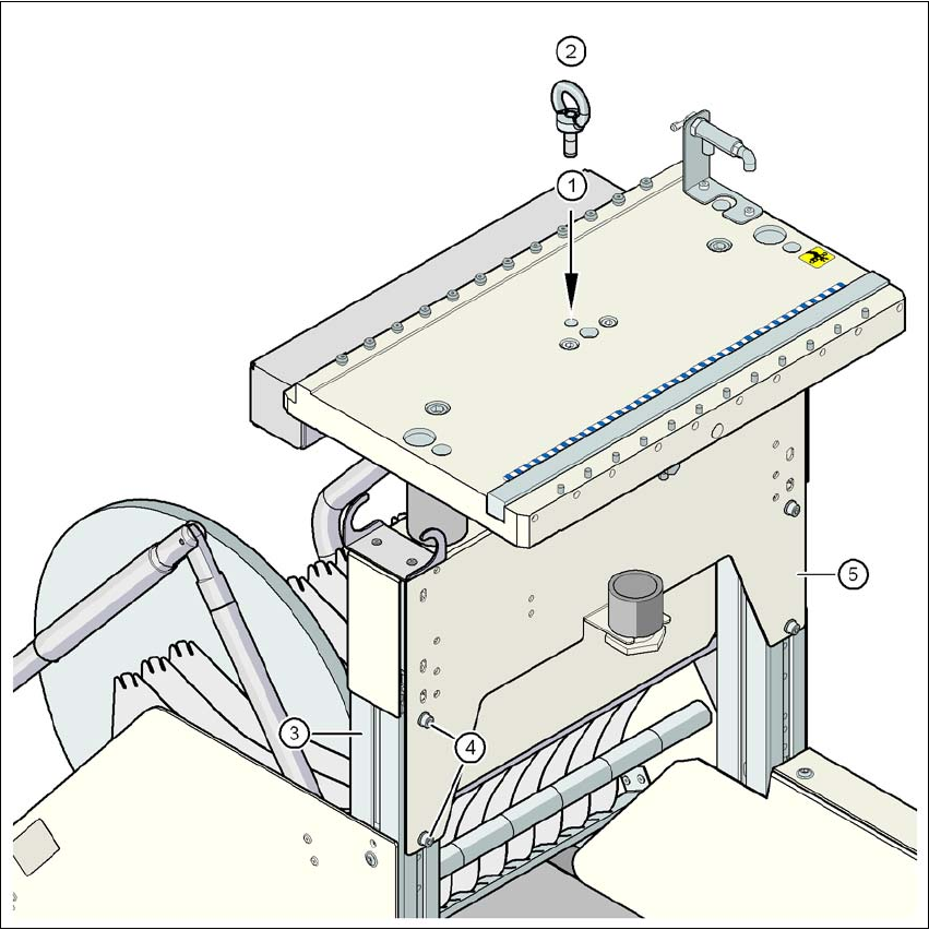
→ Screw the eye-bolt into the M12 hole (item 1 in Fig. 4.4 - 1
, page 182) in the component trolley
table bed.
→ Attach the hooks of the lifting device to the eye-bolt (item 2 in Fig. 4.4 - 1
, page 182).
→ Tighten the cable of the lifting device.
→ Loosen the 8 hexagon socket head screws, M6x12 (item 4 in Fig. 4.4 - 1
, page 182).
→ Raise or lower the component trolley table to the desired height,
→ Check the preset height with reference to the position of the check hole. The check hole for
the selected height must not be covered by the column.
→ If necessary, correct the height so that the holes for the fixing screws in the bridge are aligned
with the threaded holes in the vertical profiled beams (see figures on page 183
, 185, 187 and
189
.
→ Fix the bridge (item 5) to the vertical profiled beams using the 8 hexagon socket head screws
and washers. The positions of the hexagon socket head screws are shown in figures 4.4 - 2
to 4.4 - 9
.
PCB conveyor height Figure Page
830 mm 4.4 - 2
183
900 mm 4.4 - 4 185
930 mm 4.4 - 6 187
950 mm 4.4 - 8 189
4 Setting up and commissioning User manual SIPLACE D4
4.4 Adapting the component trolley to the PCB conveyor height From software version SR.605.xx 07/2008 EN Edition
182
4
Fig. 4.4 - 1 Position of the eye-bolt on the component trolley
(1) M12 hole for eye-bolt
(2) Eye-bolt, DIN 580 M12-St
(3) Vertical profiled beam
(4) Hexagon socket head screw, M6x12 with washer, 8 x
(5) Jumper