00195779-0102_UM_D4_SR605_EN.pdf - 第138页
3 Technical data for the machine User manual SIPLACE D4 3.10 Component trolley From software version SR.605.xx 07/2008 EN Edition 138 3.10.4 T ape cont ainer The tape co ntainer can hold reels up to 19" in di ameter…

User manual SIPLACE D4 3 Technical data for the machine
From software version SR.605.xx 07/2008 EN Edition 3.10 Component trolley
137
NOTE ON OPERATIONAL SAFETY 3
All component trolleys must be docked on the machine in order to operate it. If they are not, the
machine stays in EMERGENCY STOP status. The placement process is interrupted.
The communication interface (item 5 in Fig. 3.10 - 3
, page 136) supplies the necessary voltages
and control signals to the feeder modules.
The tape reel container (item 4 in Fig. 3.10 - 3
, page 136) holds tape reels up to 19" (483 mm).
The pull-out waste tape container (item 4 in Fig. 3.10 - 3
, page 136) can be found beneath the
chassis. The cut waste tape travel down a chute into the waste container, which must be regularly
emptied.
3.10.3 Technical data
3
3
Length
Length with handle folded up
Width
711 mm
871 mm
475 mm
Height of bottom edge of table bed for
830 mm PCB conveyor height
900 mm PCB conveyor height
930 mm PCB conveyor height
950 mm PCB conveyor height
680 mm
750 mm
780 mm
800 mm
PCB conveyor height 830 mm ± 15 mm (standard)
900 mm ± 15 mm (option)
930 mm ± 15 mm (option)
950 mm ± 15 mm (SMEMA option)
Weight
without feeder modules
with feeder modules at all locations
75 kg
130 kg
Reel diameter
standard
maximum
up to 432 mm (17")
483 mm (19")
Locations for feeder modules max. 12
Changeover time less than 1 min.
3 Technical data for the machine User manual SIPLACE D4
3.10 Component trolley From software version SR.605.xx 07/2008 EN Edition
138
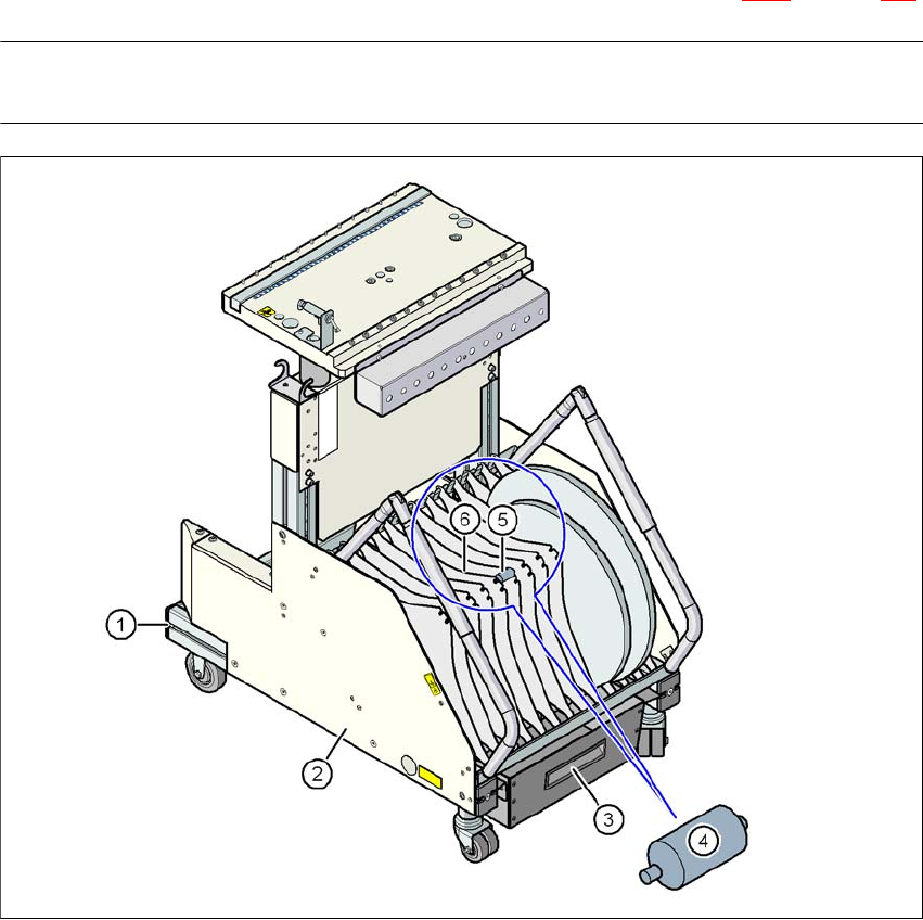
3.10.4 Tape container
The tape container can hold reels up to 19" in diameter. You should use spindles to process reels
of 15" diameter or more. The use of separating plates is described in Section 5.5.4
on page 206.
PLEASE NOTE 3
For optimum operation, we recommend the use of spindles for 15" diameter or more.
3
Fig. 3.10 - 4 Component trolley with tape container
(1) Component trolley
(2) Tape container
(3) Waste tape container
(4) Spindle (enlarged)
(5) Position of the spindles
(6) Separating plate

User manual SIPLACE D4 3 Technical data for the machine
From software version SR.605.xx 07/2008 EN Edition 3.10 Component trolley
139
3.10.4.1 Tape reel diameter in relation to the PCB conveyor height
3
3.10.5 External power supply for component trolley
Item no. 00119029-xx External power supply, CO trolley
Item no. 00119030-xx Extension cable, main power supply
To keep the time required for a setup change as short as possible, component trolleys can be set
up in advance at a special external location. The feeder module functions and setting can be
checked there to prepare for use. We provide an external power supply for this purpose. The com-
ponent trolley with the required electrical power and compressed air is supplied via a connecting
cable.
3.10.5.1 Technical data
The kit contains a main power cable to European standards, a main power cable to US standards
and a connecting cable between the power supply and the component trolley.
3.10.6 Compressed air supply for bulk case feeder modules
Item no. 00119028-xx Bulk case compressed air distributor
Bulk case feeder modules require compressed air in order to work. A compressed air supply for
bulk case feeder modules is therefore available as an option.
Option –
With support for 3rd tape
reel
PCB conveyor height
of the component trolley
Tape reel diameter Tape reel diameter
830 mm 17" 15"
900 mm 19" 17"
930 mm 19" 17"
950 mm 19" 19"
Main power voltage 230 VAC ± 5 %
120 VAC ± 5 %
Compressed air connection Max. 1.0 MPa (10 bar)
Output pressure Can be adjusted with pressure regulator