00195779-0102_UM_D4_SR605_EN.pdf - 第134页
3 Technical data for the machine User manual SIPLACE D4 3.10 Component trolley F rom software version SR.605.xx 07/2008 EN Edition 134 3.10 Component trolley Item no. 00119821-xx CO tr olley SIPLACE D4 Up to four compone…

User manual SIPLACE D4 3 Technical data for the machine
From software version SR.605.xx 07/2008 EN Edition 3.9 Feeder modules
133
3.9.13.2 Technical data
3
3
3
3.9.13.3 Parameters for surf tape feeder modules
The parameters for the surf tape feeder module can be modified on the SIPLACE Pro computer.
Tape widths 8/12/16 mm
Recommended tape and component
sizes
8 mm: for 1 x 1 mm² - 2.3 x 2.3 mm² components
12 mm: for 2.3 x 2.3 mm² - 5 x 5 mm² components
16 mm: for 3.8 x 3.8 mm² - 9.5 x 9.5 mm² compo-
nents
Packaging accuracy of the bare die on
the surf tape
Bare die size up to 2.3 x 2.3 mm²: +/- 100 µm, 6 σ
Bare die size over 2.3 x 2.3 mm²: +/- 200 µm, 6 σ
(related to the center of the pocket)
Required distance between the edges of
the bare dies to the tape pocket Min. 0.4 mm
Pusher needle Single or triple needle depending on the die size
Tape material Metric
Tape standard IEC 286-3, DIN-IEC-286, EIA 481, and JIS C 0806
Tape reel diameter 7" to 15"
Footprint of the feeder module 1 location on the component table
3 Technical data for the machine User manual SIPLACE D4
3.10 Component trolley From software version SR.605.xx 07/2008 EN Edition
134
3.10 Component trolley
Item no. 00119821-xx CO trolley SIPLACE D4
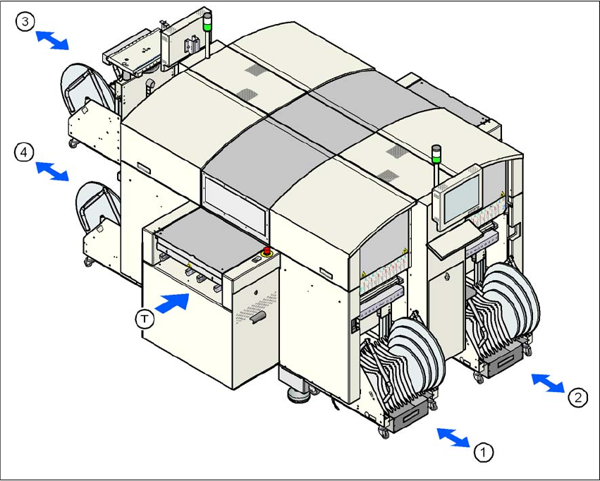
Up to four component trolleys can be docked into SIPLACE D4 machines. The locations are num-
bered as shown in the diagram below.
3
Fig. 3.10 - 1 Locations for the component trolleys
(1) Location 1
(2) Location 2
(3) Location 3
(4) Location 4
(T) PCB direction of travel
The component trolleys are stand-alone modules that can be set up with feeders at an external
set-up area. This means that the production process only has to be interrupted briefly in order to
change the component trolley.
User manual SIPLACE D4 3 Technical data for the machine
From software version SR.605.xx 07/2008 EN Edition 3.10 Component trolley
135
PLEASE NOTE: 3
At external set-up positions, you will need an external power supply for the component trolley
(see Section 3.10.5, page 139).
3
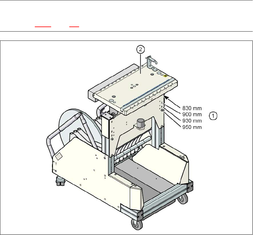
Fig. 3.10 - 2 Component trolley with a PCB conveyor height of 950 mm
3
(1) Holes for the conveyor heights of 830 to 950 mm
(2) Component table
Properties
– The trolleys move easily.
– The component trolley is fixed so precisely to the machine that it is even suitable for process-
ing 01005 components.
– The component trolley can be adjusted to PCB conveyor heights of 830 mm, 900 mm, 930
mm and 950 mm in just a few simple actions.
– The tape container can hold tape reels with a diameter of up to 15" (optional up to 19").