00195779-0102_UM_D4_SR605_EN.pdf - 第12页
Contents User manual SIPLACE D4 07/2008 EN Edition 12
User manual SIPLACE D4 Contents
07/2008 EN Edition
11
6.2.6 Positioning PCB barcode labels on the PCB . . . . . . . . . . . . . . . . . . . . . . . . . . . . . 232
6.2.6.1 Positioning along the long side of the PCB -
Scanning beam across the direction of travel . . . . . . . . . . . . . . . . . . . . . . . . . . . . 232
6.2.6.2 Positioning along the long side of the PCB -
Scanning beam along the direction of travel . . . . . . . . . . . . . . . . . . . . . . . . . . . . . 233
6.2.6.3 PCB overshoot over the machine with the dual conveyor . . . . . . . . . . . . . . . . . . . 233
6.2.6.4 Positioning along the width of the PCB -
Scanning beam across the direction of travel . . . . . . . . . . . . . . . . . . . . . . . . . . . . 234
6.2.6.5 Positioning along the width of the PCB -
Scanning beam along the direction of travel,
PCB barcode scanner 1D topside . . . . . . . . . . . . . . . . . . . . . . . . . . . . . . . . . . . . . 234
6.2.6.6 Positioning along the width of the PCB -
Scanning beam along the direction of travel,
PCB barcode scanner 1D underside . . . . . . . . . . . . . . . . . . . . . . . . . . . . . . . . . . . 235
6.3 PCB alignment . . . . . . . . . . . . . . . . . . . . . . . . . . . . . . . . . . . . . . . . . . . . . . . . . . . . . . . . . . . . . . . . 236
6.3.1 Description . . . . . . . . . . . . . . . . . . . . . . . . . . . . . . . . . . . . . . . . . . . . . . . . . . . . . . . 236
6.4 SMEMA adapter box . . . . . . . . . . . . . . . . . . . . . . . . . . . . . . . . . . . . . . . . . . . . . . . . . . . . . . . . . . . 237
6.5 Package for splice detection . . . . . . . . . . . . . . . . . . . . . . . . . . . . . . . . . . . . . . . . . . . . . . . . . . . . 237
6.6 Long board. . . . . . . . . . . . . . . . . . . . . . . . . . . . . . . . . . . . . . . . . . . . . . . . . . . . . . . . . . . . . . . . . . . 238
6.7 Magnetic pin support . . . . . . . . . . . . . . . . . . . . . . . . . . . . . . . . . . . . . . . . . . . . . . . . . . . . . . . . . . 239
6.8 Component sensor for the C&P12 head . . . . . . . . . . . . . . . . . . . . . . . . . . . . . . . . . . . . . . . . . . . 240
6.8.1 Description . . . . . . . . . . . . . . . . . . . . . . . . . . . . . . . . . . . . . . . . . . . . . . . . . . . . . . . 241
6.8.2 Measuring conditions . . . . . . . . . . . . . . . . . . . . . . . . . . . . . . . . . . . . . . . . . . . . . . . 241
6.9 C&P high-resolution CO camera, type 29, 27 x 27, digital. . . . . . . . . . . . . . . . . . . . . . . . . . . . . 243
6.9.1 Structure. . . . . . . . . . . . . . . . . . . . . . . . . . . . . . . . . . . . . . . . . . . . . . . . . . . . . . . . . 243
6.9.2 Technical data . . . . . . . . . . . . . . . . . . . . . . . . . . . . . . . . . . . . . . . . . . . . . . . . . . . . 243
6.10 01005 package . . . . . . . . . . . . . . . . . . . . . . . . . . . . . . . . . . . . . . . . . . . . . . . . . . . . . . . . . . . . . . . . 244
6.11 0201 package . . . . . . . . . . . . . . . . . . . . . . . . . . . . . . . . . . . . . . . . . . . . . . . . . . . . . . . . . . . . . . . . . 244
6.12 Vacuum pump . . . . . . . . . . . . . . . . . . . . . . . . . . . . . . . . . . . . . . . . . . . . . . . . . . . . . . . . . . . . . . . . 245
6.13 SIPLACE Productivity Lift. . . . . . . . . . . . . . . . . . . . . . . . . . . . . . . . . . . . . . . . . . . . . . . . . . . . . . . 246
6.13.1 Concept of parallel placement . . . . . . . . . . . . . . . . . . . . . . . . . . . . . . . . . . . . . . . . 246
6.13.2 Implementing parallel placement . . . . . . . . . . . . . . . . . . . . . . . . . . . . . . . . . . . . . . 247
6.13.3 Advantages of the productivity lift. . . . . . . . . . . . . . . . . . . . . . . . . . . . . . . . . . . . . . 248
6.14 Vision Teach Station . . . . . . . . . . . . . . . . . . . . . . . . . . . . . . . . . . . . . . . . . . . . . . . . . . . . . . . . . . . 249
6.14.1 Description . . . . . . . . . . . . . . . . . . . . . . . . . . . . . . . . . . . . . . . . . . . . . . . . . . . . . . . 250
6.14.2 Advantages . . . . . . . . . . . . . . . . . . . . . . . . . . . . . . . . . . . . . . . . . . . . . . . . . . . . . . 250
6.14.3 Which component cameras are supported?. . . . . . . . . . . . . . . . . . . . . . . . . . . . . . 251
Contents User manual SIPLACE D4
07/2008 EN Edition
12
User manual SIPLACE D4 1 Introduction
From software version SR.605.xx 07/2008 EN Edition
13
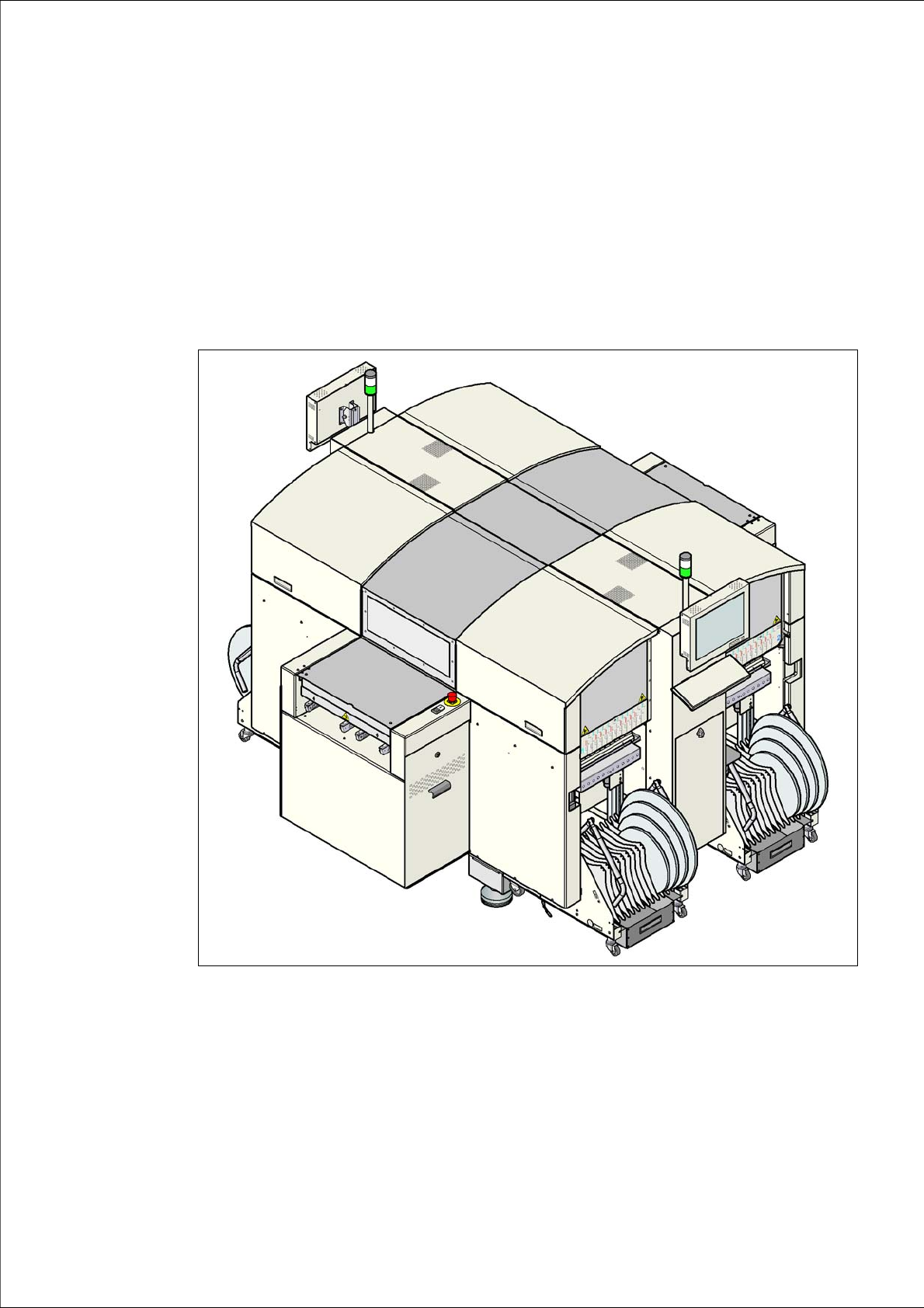
1 Introduction
These operating instructions provide a manual or reference work for operating and setting up the
SIPLACE
®
D4 placement machine.
The header of each chapter contains the release and software version, to which this manual ap-
plies.
1
Fig. 1.0 - 1 SIPLACE D4 placement machine