00195779-0102_UM_D4_SR605_EN.pdf - 第113页
User manual SIPLACE D4 3 Technical data for the machine From software version SR.605.xx 07/2008 EN Edition 3.7 PCB conveyor system 113 3.7.7 Definition of the PCB warpage 3.7.7.1 PCB warp age on the conveyor PCB warpage …
3 Technical data for the machine User manual SIPLACE D4
3.7 PCB conveyor system From software version SR.605.xx 07/2008 EN Edition
112
3.7.6 Configuration options
3.7.6.1 PCB single conveyor
Item no. 00119940-xx D4 modular single conveyor
Item no. 00119626-xx Stationary conveyor side, right HF/X/D
Item no. 00119928-xx Stationary conveyor side, left HF/X/D
Item no. 00119631-xx Conveyor width 242/508 mm (Wide board), D1/D2/D3/D4
Item no. 00119086-xx Conveyor height 900 mm, D4
Item no. 00119083-xx Conveyor height 930 mm, D4
Item no. 00119082-xx Conveyor height 950 mm, D4
3.7.6.2 Flexible PCB dual conveyor
Item no. 00119942-xx D4 modular dual conveyor
Item no. 00119626-xx Stationary conveyor side, right HF/X/D
Item no. 00119928-xx Stationary conveyor side, left HF/X/D
Item no. 00119631-xx Conveyor width 242/508 mm (Wide board), D1/D2/D3/D4
Item no. 00119086-xx Conveyor height 900 mm, D4
Item no. 00119083-xx Conveyor height 930 mm, D4
Item no. 00119082-xx Conveyor height 950 mm, D4
User manual SIPLACE D4 3 Technical data for the machine
From software version SR.605.xx 07/2008 EN Edition 3.7 PCB conveyor system
113
3.7.7 Definition of the PCB warpage
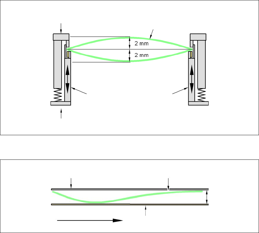
3.7.7.1 PCB warpage on the conveyor
PCB warpage across the direction of travel max. 1 % of the PCB diagonal, but not exceeding 2 mm
3
PCB warpage in direction of travel + PCB thickness < 5.5 mm
3
3
Fixed clamped edge
Movable clamping device
Printed circuit board
Conveyor side wall
Fixed clamped edge
Conveyor belt
Printed circuit board
PCB transport direc-
tion
5.5 mm
3 Technical data for the machine User manual SIPLACE D4
3.7 PCB conveyor system From software version SR.605.xx 07/2008 EN Edition
114
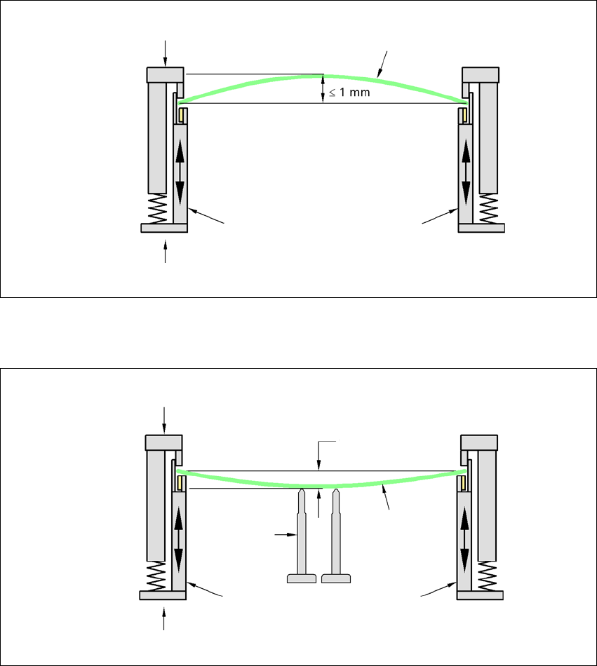
3.7.7.2 PCB warpage during placement
A warpage of 2 mm can lead to problems focusing on local fiducials and ink spots in the middle of
the PCB. The digital camera's focus is 2 mm. When all the tolerances are taken into account, this
value is reduced to 1.5 mm. Also note that the component height is reduced by the warpage.
3
3
PCB warpage down, max. 0.5 mm
3
→ Use magnetic pin supports to achieve this value.
Movable clamping device
Fixed clamped edge
Printed circuit board
Conveyor side wall
Printed circuit board
Magnetic pin
support
Movable clamping device
Fixed clamped edge
Conveyor side wall
0.5 mm