00195779-0102_UM_D4_SR605_EN.pdf - 第240页
6 Station extensions User manual SIPLACE D4 6.8 Component sensor for the C&P12 head From software ver sion SR.605.xx 07/2008 EN Edition 240 6.8 Component sensor for the C&P12 head Item no. 001 18021-xx C omponent…
User manual SIPLACE D4 6 Station extensions
From software version SR.605.xx 07/2008 EN Edition 6.7 Magnetic pin support
239
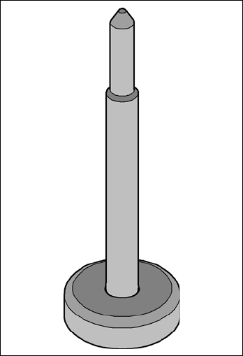
6.7 Magnetic pin support
Item no. 00119680-xx Magnetic pin support
Wide boards tend to deflect during placement such that, under certain circumstances, the compo-
nents can no longer be placed with the desired accuracy. Highly curved PCBs also affect the
placement accuracy. This problem can be easily rectified by fitting magnetic pin supports on the
lifting table.
6
Fig. 6.7 - 1 Magnetic pin support
6 Station extensions User manual SIPLACE D4
6.8 Component sensor for the C&P12 head From software version SR.605.xx 07/2008 EN Edition
240
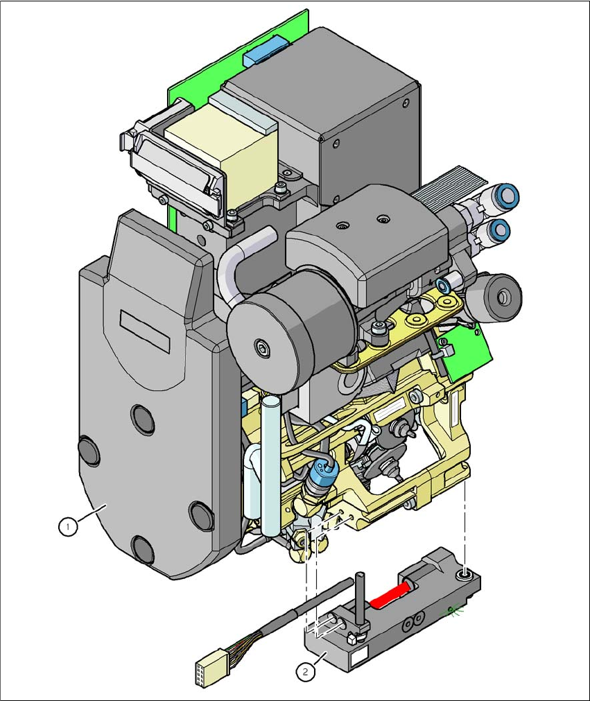
6.8 Component sensor for the C&P12 head
Item no. 00118021-xx Component sensor for the 12-segment C&P head
6
Fig. 6.8 - 1 12-segment Collect&Place head with component sensor
(1) 12-segment Collect&Place head
(2) Component sensor
User manual SIPLACE D4 6 Station extensions
From software version SR.605.xx 07/2008 EN Edition 6.8 Component sensor for the C&P12 head
241
6.8.1 Description
The component sensor is fixed to the bottom of the housing of the 12-segment Collect&Place
head (see Fig. 6.8 - 1
, page 240). It scans the outline of a component and checks whether there
is a component at the nozzle. It also determines the height of the component. This data can be
used to determine whether the component is in the normal position or on edge at the nozzle. Com-
ponent heights from 0.1 to 4 mm can be checked. For larger components, only the presence of
the component at the nozzle is checked.
The component sensor is configured in the package form editor on the SIPLACE Pro computer.
Every nozzle, including the special nozzles, can be scanned by the component sensor.
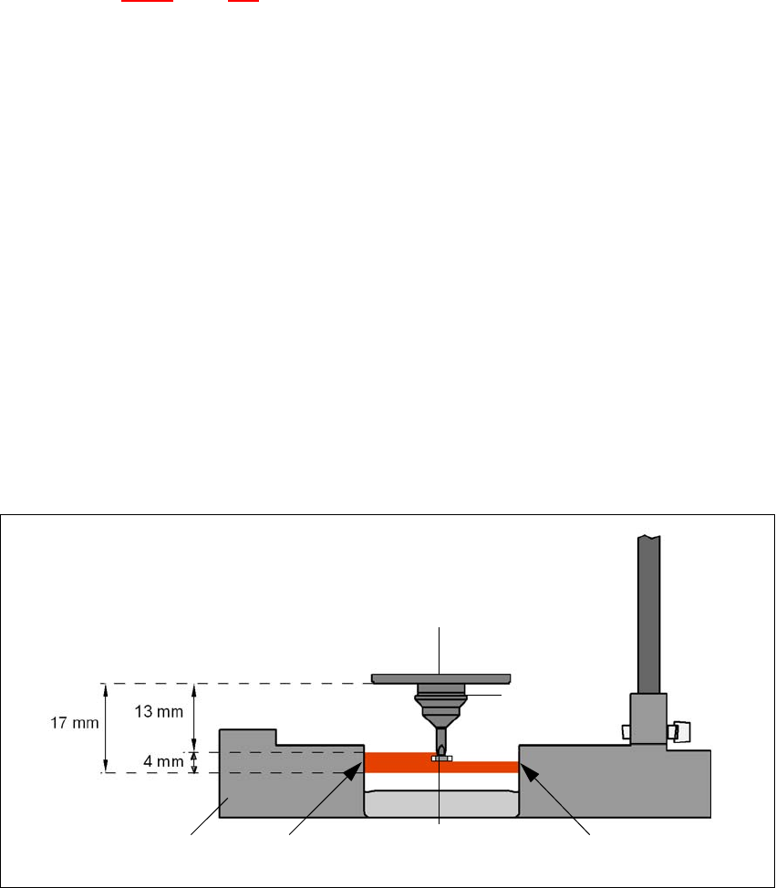
6.8.2 Measuring conditions
The two following conditions must be fulfilled in order to obtain a valid measurement:
– The light beam must touch the empty nozzle tip during the calibration process.
– The nozzle tip must be inside the light beam when it is holding a component.
– Minimum nozzle length 13 mm
– Nozzle length + component height + tolerance < 17 mm
If these conditions are fulfilled, it is possible to determine whether a component is present or ab-
sent, or to measure the component height. The minimum difference in height is 100 µm.
6
Fig. 6.8 - 2 Component sensor, working principle
Incremental disk
Component
Nozzle
IR LED PhototransistorCross-section through
component sensor